Overall heating device for automotive stabilizer bar with variable-section end part

A technology of overall heating and stabilizing rods, which is applied in the direction of heat treatment furnace, heat treatment equipment, process efficiency improvement, etc., to achieve the effect of precise control of heating temperature, avoiding fatigue failure, and avoiding heat energy waste

Active Publication Date: 2014-03-26
安庆市恒瑞达汽车零部件制造有限公司
View PDF5 Cites 5 Cited by
  • Summary
  • Abstract
  • Description
  • Claims
  • Application Information

AI Technical Summary

Problems solved by technology

[0004]In production, in order to facilitate the connection between the stabilizer bar and the car suspension, the end of the stabilizer bar needs to be forged into a certain shape, which will make the end section of the stabilizer bar There is a large difference in the shape of the cross section of the stabilizer rod body. When the traditional resistance heating method is used to clamp the end part, due to the different cross-sectional shape, the resistance generated is different, resulting in uneven heating, and the end part is easy to be fused
In order to prevent the end of the stabilizer bar from being fused during the production of variable cross-section stabilizer bars, the heating electrode only clamps and heats the middle part of the stabilizer bar, but cannot heat the ends of the stabilizer bar. After the heat treatment of the stabilizer bar, the hardness of the two end parts Low, the metallographic structure has not changed, the performance of the end of the stabilizer bar is inconsistent with the heated part of the stabilizer bar, the mechanical properties of the end are low, the end of the stabilizer bar is prone to fatigue failure during driving, and the hidden dangers of driving safety increase

Method used


Image

  • Overall heating device for automotive stabilizer bar with variable-section end part

Examples


Embodiment approach

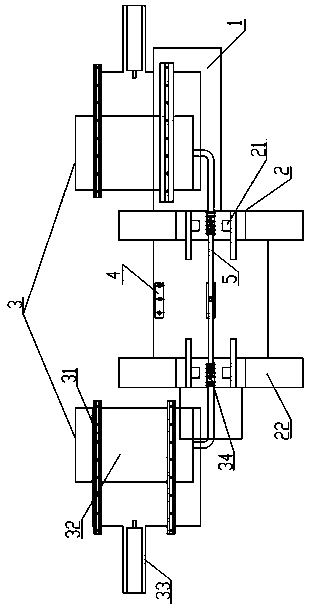
[0022] figure 1 A preferred embodiment of the overall heating equipment of the automobile stabilizer bar of the present invention is shown. The heating device 2 is provided with two pairs of heating electrodes 21 , and the heating electrodes are arranged on the frame 1 through two electrode supports 22 , and can clamp and heat the middle part of the stabilizing rod 5 . Described supersonic heating device 3 quantity is two and is symmetrically arranged on both sides of frame 1, and supersonic heating device 3 comprises supersonic heating machine 32, and this supersonic heating machine is arranged on two rolling linear guide rails 31, rolling straight line The guide rail 31 is arranged on the frame 1, and the rolling linear guide 31 is a narrow rolling linear guide with equal load in four directions, which can ensure that the reciprocating linear motion of the super audio heating machine 3 is stable and reliable; the rolling linear guide 31 is also provided with a cylinder 33, ...


PUM


Abstract

The invention provides an overall heating device for an automotive stabilizer bar with a variable-section end part. The overall heating device for the automotive stabilizer bar with the variable-section end part comprises a frame (1), and a superaudio heating device (3) provided with a resistance heating device (2) and is used for heating the end of the stabilizer bar, wherein the superaudio heating device (3) comprises a rolling linear guide rail (31); a superaudio heater (32) is arranged on the guide rail; the superaudio heater (32) can be driven by a cylinder (33) to move on the rolling linear guide rail (31); a heating end (34) for heating the stabilizer bar end is arranged on the superaudio heater (32); a heating power supply is controlled through a temperature detector (4). The overall heating device heats the middle part of the stabilizer bar through electrodes first, and then heats the end of the stabilizer bar through the superaudio heating device after a set temperature is reached, so that the same heating temperature can be kept at the middle part and the end part of the stabilizer bar, and in the heat treatment process, the end part and the middle part of the stabilizer bar have consistent metallographic structural transformation and the same hardness; after the stabilizer bar is processed, fatigue failure of the stabilizer bar can be avoided.

Description

technical field [0001] The invention relates to a heating device for an automobile stabilizer bar, in particular to an integral heating device for an automobile stabilizer bar with variable end sections. [0002] [0003] Background technique [0004] At present, in the production industry of automobile stabilizer bars, a commonly used process is to first conduct resistance heating on the stabilizer bar blank, and then use a special forming machine to bend it in a hot state, and then quench it. Among them, the device usually used in resistance heating includes two pairs of heating electrodes. Select the electrode clamping point at the middle part of the two ends of the stabilizer bar at a certain distance from the end, place the rod body, and the heating electrodes clamp the stabilizer bar. In this way, the two pairs The part of the rod body between the heating electrodes and the electrodes form a loop, and the middle part of the stabilizer rod is equivalent to a resistor. ...

Claims


Application Information

Patent Timeline
Patent Type & Authority Applications(China)
IPC IPC(8): C21D9/00C21D1/42C21D1/40
CPCY02P10/25
Inventor 吴力伟
Owner 安庆市恒瑞达汽车零部件制造有限公司
Why Eureka
Try Eureka