Double-web H-shaped steel type buckling restraint brace

A buckling restraint, H-beam technology, applied in the direction of building components, earthquake resistance, etc., can solve the problem of not taking into account, and achieve the effect of reducing the buckling length, reducing the amount of steel used, and excellent performance

Active Publication Date: 2014-03-26
SHANGHAI BAOYE GRP CORP
View PDF6 Cites 3 Cited by
  • Summary
  • Abstract
  • Description
  • Claims
  • Application Information

AI Technical Summary

Problems solved by technology

In order to prevent the local buckling instability damage of the supporting core unit, it is not necessary to adopt stiffening restraint measures. If an appropriate core s

Method used


Image

  • Double-web H-shaped steel type buckling restraint brace
  • Double-web H-shaped steel type buckling restraint brace
  • Double-web H-shaped steel type buckling restraint brace

Examples


Embodiment Construction

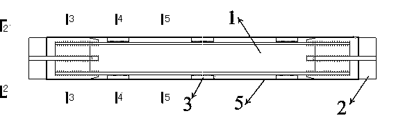
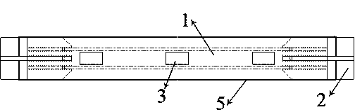
[0022] like Figure 1-Figure 6 Shown: a double-web H-shaped steel buckling-constrained support, which includes a double-web H-shaped steel 1 and a rectangular sleeve 5 sleeved outside the double-web H-shaped steel;

[0023] The double-web H-shaped steel can be a box-shaped body in which two H-shaped steels are butted through their notches.

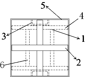
[0024] The flange 4 of the double-web H-shaped steel and the middle parts of both ends of the two webs 6 are provided with symmetrical grooves respectively, and cross-shaped stiffeners 2 are welded in the grooves, such as Figure 7 As shown: the cross-shaped stiffener 2 is welded vertically by two flat plates 7 with grooves;

[0025] The inner wall of the sleeve 5 is provided with at least two pairs of channel steels 3 , each pair of channel steels is arranged with their backs facing each other, and their backs respectively press against both sides of the double-web H-shaped steel flanges.

[0026] like Figure 8 Shown: the buckling-co...


PUM


Abstract

The invention relates to a double-web H-shaped steel type buckling restraint brace comprising double-web H-shaped steel and a rectangular sleeve covering outside the double-web H-shaped steel. Grooves are symmetrically formed in the middles of two ends of flanges and two webs of double-web H-shaped steel respectively, and cross reinforced ribs are welded in the grooves. At least two pairs of channel steel are arranged on the inner wall of the sleeve and arranged in a backing manner, and backs of the channel steel are butted against two sides of the flanges of the double-web H-shaped steel. Each of the cross reinforced rib consists of two flat plates with grooves in a perpendicular welding manner. By the double-web H-shaped steel type buckling restraint brace, the buckling length of a core energy consumption unit is reduced, the integral stability thereof is guaranteed, steel usage is reduced to the utmost extent, and the buckling restraint brace has the advantages of flexible design, low manufacturing cost, excellent performance and high adaptability.

Description

technical field [0001] The invention relates to a buckling constrained support, in particular to a double web H-shaped steel buckling constrained support. Background technique [0002] Earthquakes are extremely destructive and random, and will pose a huge threat to human life and property safety. The traditional seismic design relies on the structure itself to resist the earthquake. The main structure will inevitably be damaged or destroyed in the earthquake, which will affect the normal function of the structure and lead to the occurrence of secondary disasters. Installing energy-dissipating shock-absorbing devices for building structures is an effective means to reduce structural earthquake damage. It can absorb a large amount of energy during an earthquake and concentrate the damage on the energy-dissipating shock-absorbing devices themselves, thereby protecting the main structure and reducing the number of key parts of the structure. The effect of structural damage. ...

Claims


Application Information

Patent Timeline
IPC IPC(8): E04B1/98
Inventor 郭小康许立新陈桥生朱卫军
Owner SHANGHAI BAOYE GRP CORP
Why Eureka
Try Eureka