Energy dissipation device

a technology of energy dissipation device and energy dissipation tube, which is applied in the direction of steering control, vibration damper, steering control, etc., can solve the problems of poor damper performance, poor accuracy of machined parts and end seals, and difficulty in repair, so as to achieve the effect of improving performan

Inactive Publication Date: 2018-04-19
UNIVERSITY OF CANTERBURY
View PDF29 Cites 7 Cited by
  • Summary
  • Abstract
  • Description
  • Claims
  • Application Information

AI Technical Summary

Benefits of technology

[0025]An energy dissipation device may be used alone, or could be used in combination with other devices for enhanced performance.

Problems solved by technology

Viscous fluid dampers do not experience low-cycle fatigue and can generally accommodate large seismic displacements, but require specialist materials, require specialist manufacturing processes and highly accurate machined parts and end seals, and for these reasons are expensive.
Mechanical buckling restrained braces (BRBs) are more affordable than viscous dampers and can accommodate large displacements but after several cycles are susceptible to low cycle fatigue which can lead to failure of the brace.
In addition, commonly available dampers tend to be heavy and difficult to repair.
Generally, buckling restrained braces do not have equal force in tension and compression, resulting in a phenomena called ‘overstrength of the brace’.
Overstrength behaviour can damage structural members that the BRB is connected to, or adjacent connections.
To compensate, the connections and other structural members must incorporate an overstrength factor resulting in bigger sections, which increases the cost.
Due to these factors, the manufacturing process of an ideal BRB requires accurate machined parts and special details such as fused length of the bar and end connections, which also contribute to the final cost.

Method used


Image

  • Energy dissipation device
  • Energy dissipation device
  • Energy dissipation device

Examples


second embodiment

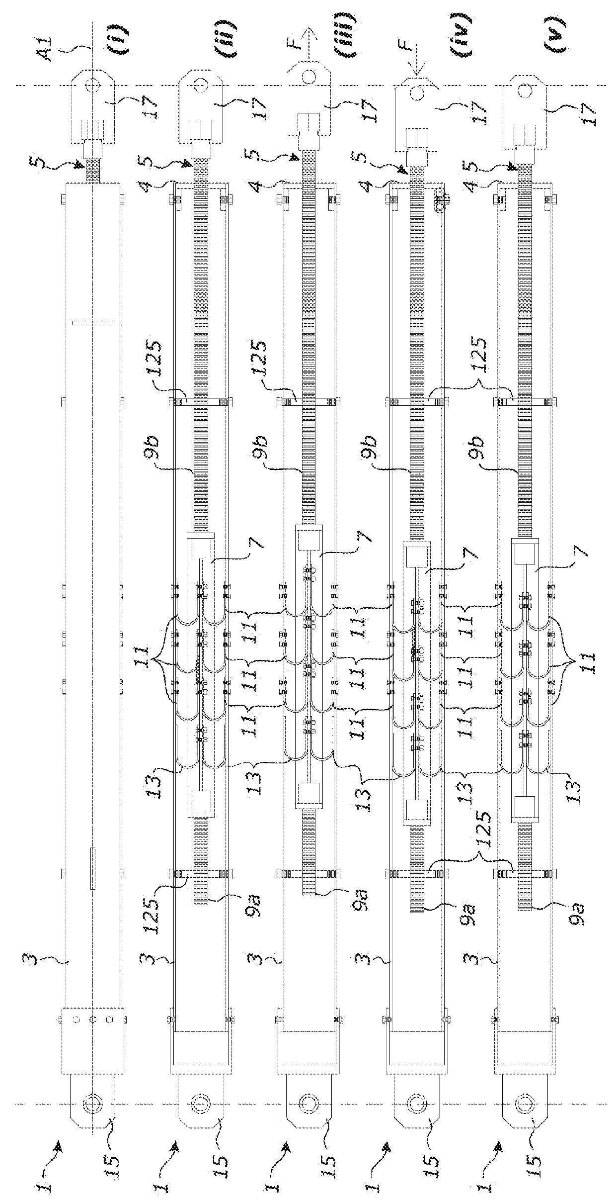
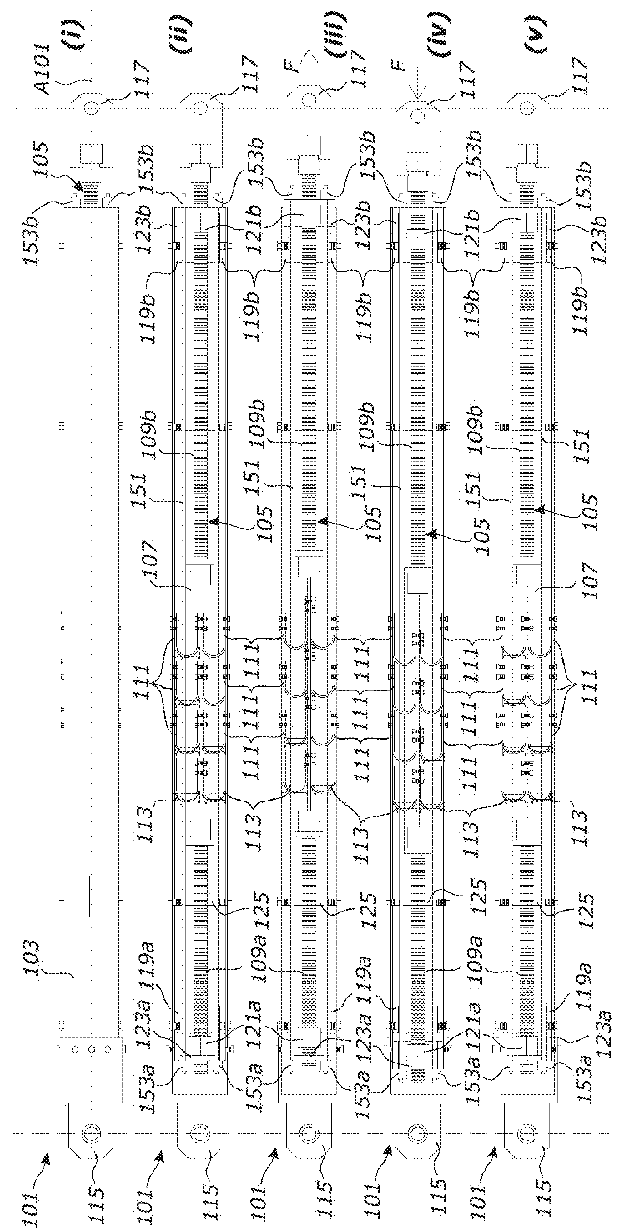
[0090]The first and second members 103, 105, each have two respective stops 119a, 119b, 121a, 121b that limit inward movement of the end caps 123a, 123b. The stops 119a, 119b on the first members 103 are shoulders that protrude inwardly from the walls of the square hollow section. The stops 121a, 121b on the second member 105 are nuts threaded onto the second member rods 9a, 9b. FIGS. 2(ii) to 2(v) illustrate operation of the second embodiment brace 101 during an earthquake. FIG. 2(ii) shows the brace 101 in a neutral position, in which the bolted UFPs 111 are unflexed. In this position, each movable end cap 123a, 123b is in contact a respective stop 119a, 119b on the first member 103 and a respective stop 121a, 121b on the second member 105.

[0091]From the neutral position shown in FIG. 2(ii), seismic forces may cause tensile loading and extension of the brace 101 as shown in FIG. 2(iii). As the brace 101 extends, the UFPs 111 connected between the first and second members 103, 105 ...

embodiment 201

[0113]Other types of supplementary dissipaters could be used in place of the grooved dissipaters. For example, FIG. 5(ii) shows an embodiment 201″ in which the supplementary dissipater comprises a slotted-bolt connection between the first end connector and the first member. The connection comprises two parallel cap plates 267 fixed relative to the first end connector 215″. The cap plates 267 have aligned slot shaped apertures 269. A washer 273 and bolt 275 arrangement bolts the cap plates 267 to the first member 203″ through the slots 269.

[0114]Metal plates 271 such as brass shims are positioned between the cap plates 267 and the first member 203″. The first member 203″ and the friction plates 271 have apertures that correspond to the bolt diameter, for receiving the shank of the bolt. The bolts 275 clamp the plates 271 between the first member 203″ and the cap plates 267 creating a friction connection. As the brace 201″ is stretched or compressed, the bolts 275 will slide longitudi...

fourth embodiment

[0122]FIGS. 8(i) to 8(vii) show a further alternative embodiment energy dissipation device 301 according to the invention. The device 301 is a self-centring multi-performance brace having a longitudinal axis A301. Unless otherwise specified, the brace components have the same functionality as those described above in relation to the embodiments of FIGS. 1(i) to 3(vii), but are designated with like reference numerals starting from 301.

[0123]Compared to the self-centring brace 101 of FIGS. 2(i) to 2(v), the brace 301 additionally comprises a plurality of supplementary dissipaters 355 at one end of the brace 301. The supplementary dissipaters are grooved dissipaters 355 as described above in relation to the multi-performance embodiment of FIGS. 3(i) to 3(vii) and FIG. 4.

[0124]The grooved dissipaters 355 cause the brace 301 to behave differently under different level earthquakes and provide extra energy dissipation to the UFPs 311 and tendons 351 in the brace 301 and protects the tendon...


PUM


Abstract

An energy dissipation device having a longitudinal axis, with first and second members that are movable longitudinally relative to each other upon an axial load applied along the longitudinal axis of the device. A plurality of U-shaped flexural plates (UFPs) are arranged between the first and second members in the longitudinal direction of the device and operatively attached to the first and second members and configured to flex upon relative movement of the first and second members. An energy dissipation device may have at least one redundant yielding-type energy dissipater connected to one but not both of the first and second members.

Description

FIELD OF THE INVENTION[0001]This invention relates to an energy dissipation device such as a damper or brace, for use in structures to absorb seismic and / or wind loads.BACKGROUND[0002]Dampers, braces, energy dissipaters, or mechanical dissipative fuses are used in structures to limit vibration induced by winds or to dissipate energy generated by seismic events.[0003]Energy dissipaters can be used in different configurations in building and bridge structures. For example, as bracing to provide lateral resistance against wind and / or earthquake loads, or between two adjacent structural members to absorb energy through a vertical shear sliding mechanism.[0004]Many types of metallic and viscous dampers or energy dissipaters are available in the market. Viscous fluid dampers do not experience low-cycle fatigue and can generally accommodate large seismic displacements, but require specialist materials, require specialist manufacturing processes and highly accurate machined parts and end se...

Claims


Application Information

Patent Timeline
Patent Type & Authority Applications(United States)
IPC IPC(8): B60R22/28B62D1/19F16F7/12F16F7/116F16F15/03
CPCB60R22/28B62D1/195F16F7/123F16F7/116F16F15/035F16F7/08E04H9/0237E04H9/028
Inventor KEATS, GAVIN DAVIDPALERMO, ALESSANDROMASHAL, MOHAMMAD MUSTAFA
Owner UNIVERSITY OF CANTERBURY
Why Eureka
Try Eureka