Connecting device for suspended ceiling

A connecting device and suspended ceiling technology, which is applied in ceilings, building components, buildings, etc., can solve the problems of being unable to meet the requirements of the diversity of decorative board materials, the requirements of bearing capacity, and the complicated construction process, so as to simplify the on-site construction process , Easy to make, strong structure

Active Publication Date: 2014-03-26
ZHEJIANG YASHA DECORATION
View PDF7 Cites 8 Cited by
  • Summary
  • Abstract
  • Description
  • Claims
  • Application Information

AI Technical Summary

Problems solved by technology

The above-mentioned suspended ceiling is generally of the exposed keel structure, that is, the ceiling board is placed on the ceiling board connecting block, and there are defects in the decorative and beautiful effect; if it is converted into a hidden keel ceiling structure, the bending performance of the decorative board itself is required. The use of decorative panels with low self-weight such as metal and PVC materials cannot meet the requirements for the diversity of decorative panel materials in decoration. If you encounter heavy medium-sized and heavy-duty decorative panels, you cannot meet the requirements for bearing capacity.
In addition, the ceiling structure using the above-mentioned ceiling connection device still has the disadvantages of large amount of work on site and complicated construction technology.

Method used


Image

  • Connecting device for suspended ceiling
  • Connecting device for suspended ceiling

Examples


Embodiment Construction

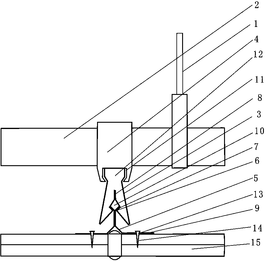
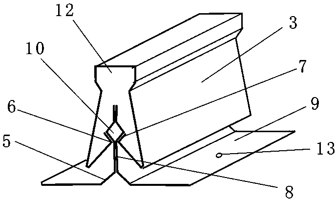
[0012] Such as figure 1 , figure 2 As shown, the ceiling connecting device of the present invention includes a suspender 1, a main keel 2 and a secondary keel 3, the upper end of the suspender 1 is fixed on the building body, and the lower end is fixed with the main keel 2, and the main keel 2 is connected There is a connecting piece 4, and the upper end of the secondary keel 3 is fixed with the connecting piece 4. The fixing structure between the upper end of the secondary keel 3 and the connecting piece 4 is as follows: the lower part of the connecting piece 4 has a T-shaped opening 11 in section, the upper end of the secondary keel 3 has a T-shaped structure 12, and the secondary keel The upper end of the sub-keel 3 has a T-shaped structure 12 that matches the lower T-shaped opening 11 of the connector 4, and the upper end of the secondary keel 3 has a T-shaped structure 12 that falls into the lower T-shaped opening 11 of the connector 4 middle. Since the above structur...


PUM


Abstract

The invention discloses a connecting device for a suspended ceiling. The connecting device for the suspended ceiling comprises a suspension rod, a primary keel and a secondary keel, wherein the upper end of the suspension rod is fixed to a building body, the lower end of the suspension rod is fixedly connected with the primary keel, a connecting piece is connected to the primary keel, and the upper end portion of the secondary keel is fixedly connected with the connecting piece. The connecting device for the suspended ceiling further comprises two suspension pieces, wherein an inward and upward bent portion is arranged on the secondary keel to form a clamping groove, an overturned edge is arranged at the tail end of the clamping groove, each suspension piece comprises a vertical secondary keel connecting piece and a transverse suspended ceiling plate fixing surface, the vertical secondary keel connecting pieces of the two suspension pieces abut against each other, each secondary keel connecting piece of the two suspension pieces is provided with a buckling structure which expands outwards, the vertical secondary keel connecting pieces of the two suspension pieces are inserted into the clamping groove of the secondary keel, and the lower ends of the buckling structures of the secondary keel connecting pieces of the two suspension pieces abut against the overturned edge arranged at the tail end of the clamping groove of the secondary keel. According to the structure of the connecting device for the suspended ceiling, the structure is firm, the requirement for diversity of materials of decorative sheets in the process of decoration can be met, the project amount on the site can be reduced, and the site construction technology is simplified.

Description

technical field [0001] The invention relates to a suspended ceiling structure in a building, more specifically a connection device for a suspended ceiling, which belongs to the technical field of architectural decoration. Background technique [0002] The suspended ceiling is one of the most common decorative structures in interior decoration. The suspended ceiling structure usually includes a suspended ceiling connection device and a ceiling board. The suspended ceiling connection device is fixed on the building body and provides a fixing place for the ceiling board. The ceiling board is generally decorated with gypsum board and light metal. board, PVC decorative board, etc. [0003] The most common existing ceiling connection device is a structure including a boom, a main keel and a secondary keel. The upper end of the boom is fixed on the building body, and the lower end is fixed to the main keel. A connecting piece is connected to the main keel. The lower part has a "T"...

Claims


Application Information

Patent Timeline
Patent Type & Authority Applications(China)
IPC IPC(8): E04B9/06
Inventor 徐法胜周东珊黄慧余广
Owner ZHEJIANG YASHA DECORATION
Why Eureka
Try Eureka