Visible microwave dryer

A microwave dryer and microwave technology, applied in the direction of drying solid materials, drying, lighting and heating equipment, etc., can solve the problem of not being able to check the drying state, and achieve the effects of convenient viewing, clear images, and high safety

Inactive Publication Date: 2014-03-26
南京研正微波设备厂
View PDF8 Cites 2 Cited by
  • Summary
  • Abstract
  • Description
  • Claims
  • Application Information

AI Technical Summary

Problems solved by technology

[0002] The microwave dryer uses microwaves, a high-frequency wave, to change at a speed of 2.4 billion times per second, causing high-speed wheel pendulum motion of water molecules, and they rub against each other to generate great heat, which is convenient f

Method used


Image

  • Visible microwave dryer

Examples


Example Embodiment

[0015] The present invention will be further explained below in conjunction with the drawings.

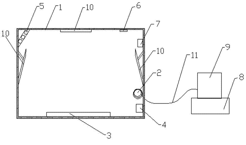
[0016] Such as figure 1 As shown, a visual microwave dryer includes a chassis 1, a microwave generator 2, a drying plate 3, a microwave control system 4 for controlling the microwave generator, an LED 5, a camera 6, a temperature sensor 7, a remote control device 8 and Remote display device 9.

[0017] LED5, camera 6 and temperature sensor 7 are connected to remote control device 8, remote display device 9 and remote control device 8 are connected, LED5, camera 6 and temperature sensor 7 are set inside the case, remote control device 8 and remote display The device 9 is arranged outside the case 1 and is connected to the camera 6 and the temperature sensor 7 inside the case 1 through a cable 11.

[0018] The outer surface of the temperature sensor 7 and the outer surface of the camera 6 are provided with metal protective nets to prevent microwaves from affecting the temperature sensor 7...


PUM


Abstract

The invention discloses a visible microwave dryer which comprises a dryer case, a microwave generator, a drying disc, a microwave control system, LEDs, a camera, a temperature sensor, a remote control device and a remote display device. Metal protective nets are arranged on the outer surface of the temperature sensor and the outer surface of a camera body, the LEDs are arranged downwards obliquely at one upper corner inside the dryer case, and mirror surfaces are arranged in the dryer case. Compared with the prior art, the visible microwave dryer is clear in image frame, convenient to use and practical.

Description

technical field [0001] The invention relates to the field of microwave drying equipment, in particular to a visible microwave drying machine. Background technique [0002] The microwave dryer uses microwaves, a high-frequency wave, to change at a speed of 2.4 billion times per second, causing high-speed wheel pendulum motion of water molecules, and they rub against each other to generate great heat, which is convenient for drying materials. , it is necessary to observe the state of the internal drying items. In the prior art, the parameters of the microwave dryer are first set, and then the items to be dried are dried. During the drying process, the drying status cannot be checked. Contents of the invention [0003] The invention overcomes the shortcomings of the prior art and provides a visual microwave dryer. [0004] In order to solve the problems of the technologies described above, the technical solution adopted in the present invention is: [0005] A visualized mic...

Claims


Application Information

Patent Timeline
IPC IPC(8): F26B25/00
Inventor 蔡远明
Owner 南京研正微波设备厂
Why Eureka
Try Eureka