This helps you quickly interpret patents by identifying the three key elements:
Problems solved by technology
Method used
Benefits of technology
Problems solved by technology
[0009] Even if the reflectance of the reflective layer is improved as in Patent Document 1, the light transmittance at the roots of the columnar crystals is low (Patent Document 2), and the original ability cannot be exerted, so it cannot be said that the improvement of the luminous brightness is sufficient. improved technology (Patent Document 3), but there is still room for improvement
Method used
Image
Click on the blue label to locate the original text in one second.
Reading with bidirectional positioning of images and text.
Examples
preparation example Construction
[0125] As the solvent that can be used in the preparation of the underlayer, for example, lower alcohols such as methanol, ethanol, n-propanol, and n-butanol; hydrocarbons containing chlorine atoms such as methylene chloride and dichloroethane; acetone, Ketones such as methyl ethyl ketone and methyl isobutyl ketone; aromatic compounds such as toluene, benzene, cyclohexane, cyclohexanone, and xylene; esters of lower fatty acids and lower alcohols such as methyl acetate, ethyl acetate, and butyl acetate; two Ethers such as alkane, ethylene glycol monoethyl, ethylene glycol monomethyl, methoxypropanol, propylene glycol monomethyl ether, propylene glycol monomethyl ether acetate, and mixtures thereof.
[0126] The thickness of the underlayer is preferably 0.1 to 10 μm, more preferably 0.5 to 5 μm. If the thickness of the backing layer is 0.5 μm or more, the adhesion to the phosphor layer is improved, and if the thickness of the backing layer is 5 μm or less, light scattering in the b...
Embodiment 1
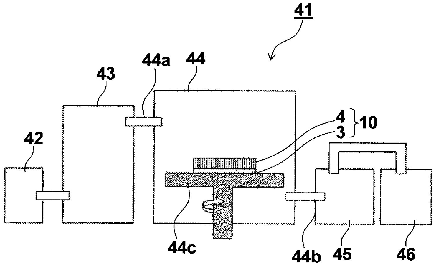
[0276] "Process of forming an underlayer on a substrate-dry process -"
[0277] The polyimide film "UPILEX-125S" (thickness 125μm) made by Ube Industries Co., Ltd. was mounted as a substrate image 3 The CVD device is formed with an underlayer made of Parylene C (manufactured by Parylene Japan, Inc.) with a melting point of 290°C on one side. The thickness of the underlayer is 3 μm. Hereinafter, a component formed by integrating the substrate and the underlayer is used as a support.
[0278] It should be noted that Parylene C has a benzene ring via -CH 2 -The basic structure formed by polymerization in which one hydrogen of the benzene ring is replaced by chlorine.
[0279] "Evaporation Process"
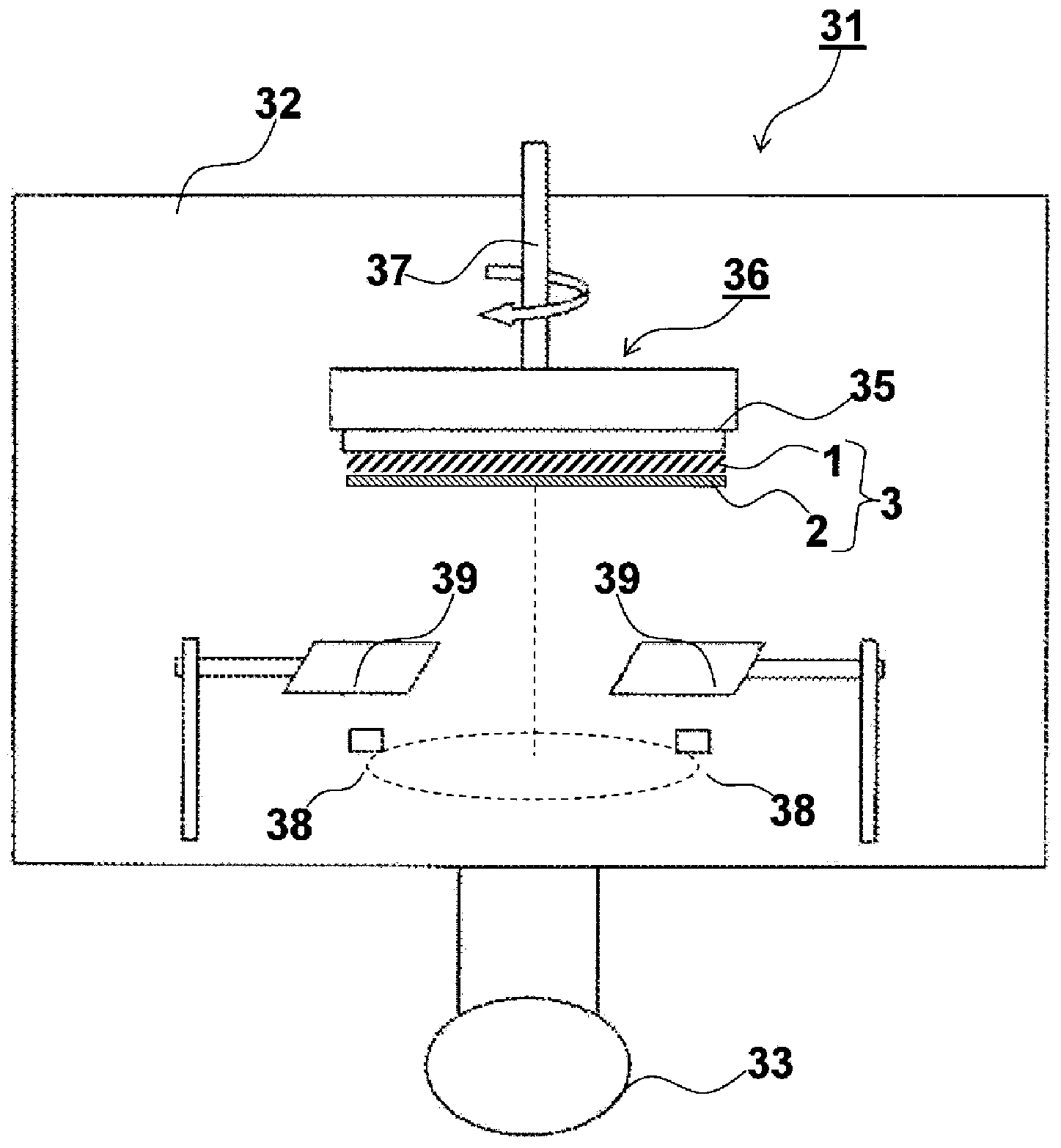
[0280] Reference figure 2 Be explained.
[0281] First, cesium iodide [CsI] and activator (TlI), which are the parent compound of the phosphor, are respectively filled into two resistance heating crucibles, and they are used as the evaporation source (38). The metal of the support bracket (...
Embodiment 2
[0310] In Example 1, except that the degree of vacuum was changed from 0.05 Pa to 0.1 Pa, the scintillator plate was manufactured in the same manner as in Example 1.
PUM
Abstract
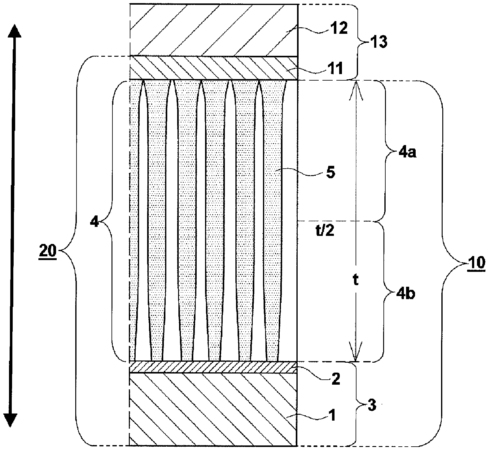
The object of the present invention is to provide a scintillator plate and a radiation detection panel demonstrating excellent light emission luminance while being limited to a thickness which maintains the sharpness required for image quality. A scintillator plate comprising an undercoat layer and a phosphor layer, wherein the phosphor layer comprises phosphor columnar crystals using the undercoat layer side as a base, and wherein when the phosphor layer is halved in terms of thickness in the lamination direction and the respective halves constitute a tip side portion and a base side portion of the phosphor columnar crystals, a ratio (B / A) of an optical transmittance (B) of the base side portion to an optical transmittance (A) of the tip side portion is not less than 70% and not more than 99%.
Description
Technical field [0001] The present invention relates to a scintillator plate that can be used in an indirect conversion method flat panel detector (FPD), a radiation detection panel composed of the scintillator plate, and a method of manufacturing them. Background technique [0002] In the past, radiographic images such as X-ray images have been widely used in the medical field for diagnosis of diseases. In particular, radiographic images based on intensified paper-film systems have achieved high sensitivity and high image quality in the long-term development. As a result, as a camera system with high reliability and excellent cost performance, it is still in the medical field worldwide. use. However, this image information is so-called analog image information, and it is impossible to perform free image processing and instantaneous transmission like digital image information that has been continuously developed in recent years. [0003] Moreover, in recent years, digitally proce...
Claims
Application Information
Patent Timeline
Application Date:The date an application was filed.
Publication Date:The date a patent or application was officially published.
First Publication Date:The earliest publication date of a patent with the same application number.
Issue Date:Publication date of the patent grant document.
PCT Entry Date:The Entry date of PCT National Phase.
Estimated Expiry Date:The statutory expiry date of a patent right according to the Patent Law, and it is the longest term of protection that the patent right can achieve without the termination of the patent right due to other reasons(Term extension factor has been taken into account ).
Invalid Date:Actual expiry date is based on effective date or publication date of legal transaction data of invalid patent.

