
Deviation rectifying method for moving head lamp effect disc

A technology of effect disk and moving head light, applied in instruments, computer control, simulators, etc., can solve problems such as difficult work, inability to align the Hall plate with the magnet, errors, etc., and achieve the effect of fast and convenient deviation correction

Active Publication Date: 2014-03-26
GUANGZHOU LEES ELECTRONICS
View PDF5 Cites 0 Cited by
  • Summary
  • Abstract
  • Description
  • Claims
  • Application Information

AI Technical Summary

Problems solved by technology

In the existing technology, due to various reasons, such as the position of the Hall plate is not set before leaving the factory, manual assembly errors, etc., the Hall plate cannot be aligned with the magnet, so that the beam cannot coincide with the color chip or the center of the pattern. In order to correct the various offsets, it is common practice to use a hammer to hit the Hall plate to fine-tune its position so that it can be aligned with the magnet on the effect plate
Using the method of beating the Hall plate to correct the deviation is not only easy to damage the Hall plate, but also difficult to work in the narrow space of the lamp

Method used


Image

  • Deviation rectifying method for moving head lamp effect disc
  • Deviation rectifying method for moving head lamp effect disc
  • Deviation rectifying method for moving head lamp effect disc

Examples


Embodiment Construction

[0025] The present invention will be further described below in conjunction with the accompanying drawings of the description.

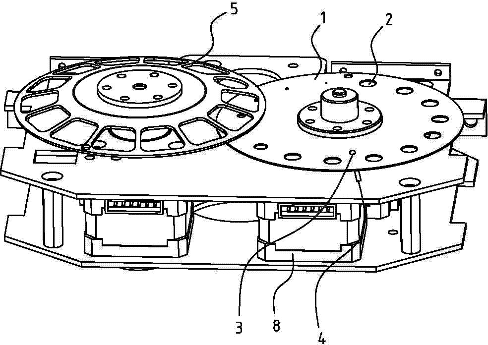
[0026] Such as figure 1 , 2 As shown, a method for correcting the deviation of the pattern wheel of the moving head light includes the following steps:

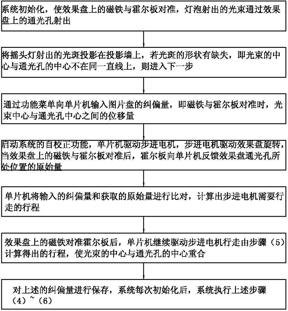
[0027] (1) System initialization, align the magnet 3 on the pattern plate 1 with the Hall plate 4, and the light beam 7 emitted by the bulb is emitted through the light hole 2 on the pattern plate 1;

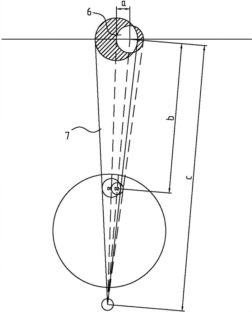
[0028] (2) if image 3 As mentioned above, project the light spot emitted by the moving head light on the projection wall, if the shape of the light spot is missing, that is, the center O1 of the beam 7 and the center O2 of the light hole 2 are not on the same straight line, then go to the next step;

[0029] (3) Input the deviation correction amount of the picture disk to the single chip microcomputer through the function menu, that is, the displacement amount between the center of the beam 7 and ...


PUM


Abstract

A deviation rectifying method for a moving head lamp effect disc includes the following steps that (1), a system is initialized; (2), light spots emitted by a moving head lamp are projected on a projection wall, and if the shapes of the light spots are defective, a next step is executed; (3), the deviation rectifying amount of a picture disc is input into a single chip microcomputer through a functional menu, and namely the deviation rectifying amount is the displacement between the light beam center and the center of a light passing hole when a magnet is directed at a Hall plate; (4), a stepped motor is driven by the single chip microcomputer to drive the effect disc to rotate, and after the magnet on the effect disc is directed at the Hall plate, the original amount of the position at which the light passing hole of the effect disc is located is fed back to the single chip microcomputer through the Hall plate; (5), the single chip microcomputer compares the input deviation rectifying amount with the obtained original amount to calculate the travel which the stepped motor needs to walk; (6), after the magnet on the effect disc is directed at the Hall plate, the single chip microcomputer continues to drive the stepped motor to walk by the travel calculated in the step (5), so that the light beam center coincides with the center of the light passing hole.

Description

technical field [0001] The invention relates to the field of LED lighting, in particular to a deviation correction method for an effect disc of a moving head lamp, such as a deviation correction method for a color chip disc and a pattern disc. Background technique [0002] LED lights are widely used in daily life due to their advantages of rich colors, long life, high luminous efficiency, energy saving and environmental protection. Since LED chips are mainly red, blue and green, in practical applications, in order to render more colorful Various lighting effects are often added to the lamps and lanterns to change the effect of the lighting effect, such as color plate, pattern plate and so on. In order to align the center of the beam with the center of the color film or pattern on the effect wheel, magnets and Hall plates are generally added to the effect wheel, and the Hall plate is used to sense the position of the magnet, and then the motor is precisely driven, and finally...

Claims


Application Information

Patent Timeline
IPC IPC(8): G05B19/042
Inventor 李治成
Owner GUANGZHOU LEES ELECTRONICS
Learn More