
Air-cooled structure for circuit breakers

An air-cooled structure, circuit breaker technology, applied in the direction of contact heating/cooling, etc., can solve the problems of reduced insulation performance of switchgear, shortened maintenance cycle, lack of pertinence, etc., to avoid personal safety accidents and limit temperature rise. , good cooling effect

Inactive Publication Date: 2016-03-02
SCHNEIDER ELECTRIC IND SAS
View PDF5 Cites 0 Cited by
  • Summary
  • Abstract
  • Description
  • Claims
  • Application Information

AI Technical Summary

Problems solved by technology

[0005] At the same time of forced air cooling, the air entering the switchgear will suck the dust in the ground into the switchgear, reducing the insulation performance of the switchgear and shortening the maintenance cycle;
[0006] This forced air cooling method needs to be supported by air ducts. The design of the air ducts is complex and not targeted. Sometimes the ingress protection (IP) level between compartments must be sacrificed to meet the flow direction of the air ducts;
[0007] Installing a fan on the top of the switchgear, and setting air ducts and ventilation holes in the switchgear will affect the internal arc performance of the switchgear;
[0008] The fan needs to be powered by a power supply drawn from the low-voltage room, and the power is relatively large

Method used


Image

  • Air-cooled structure for circuit breakers
  • Air-cooled structure for circuit breakers

Examples


Embodiment Construction

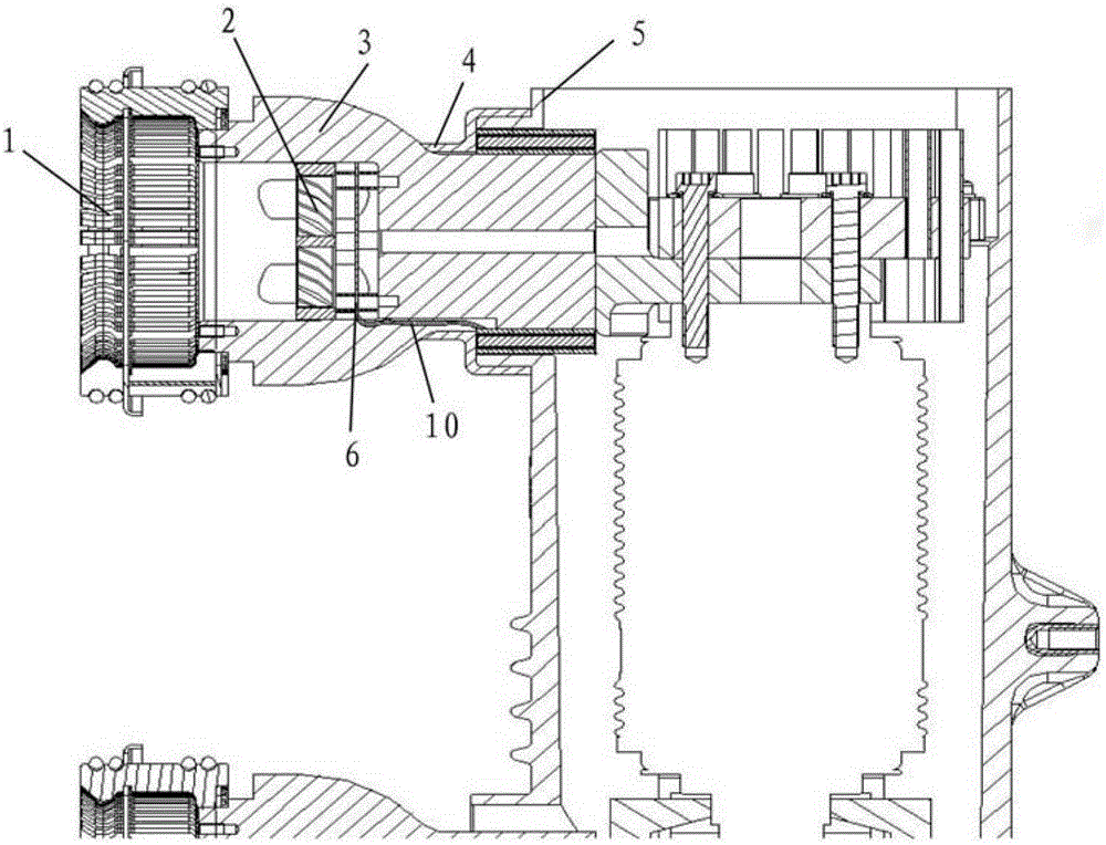
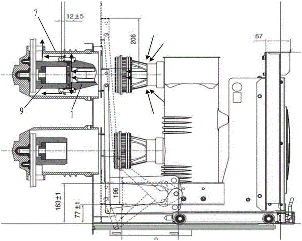
[0039] Refer below Figure 1 to Figure 2 The air-cooled structure for circuit breakers of the present invention will be further described.

[0040] figure 1 A schematic cross-sectional view of the air-cooled structure for a circuit breaker of the present invention is shown (excluding static contacts). The air-cooled structure includes a moving contact 1, a fan 2, a contact arm 3, an insulating sheath 4, an induction coil 5, a rectifying and stabilizing circuit board 6, and a static contact 9 (see figure 2 ). In this embodiment, the movable contact uses a plum blossom contact (cluster).

[0041] The moving contact 1 is fixedly connected to one end of the contact arm 3, and the fan 2 is arranged inside the contact arm 3 of the circuit breaker, and is used to supply air to the contact arm 3, the moving contact 1 and the static contact 9 of the circuit breaker to prevent them from As the temperature rises, a ventilation slot (not shown) is provided on the contact arm 3, and t...


PUM


Abstract

An air-cooled structure for a circuit breaker. The circuit breaker includes a contact arm (3), a moving contact (1) and a stationary contact (9). The moving contact (1) and the contact arm (9) 3) is fixedly connected to one end of the circuit breaker, and a fan (2) is provided inside the contact arm (3) of the circuit breaker to supply the contact arm (3), the moving contact (1) and the The static contact (9) supplies air to prevent the temperatures of the contact arm (3), the movable contact (1) and the static contact (9) from rising. A ventilation slot is provided, and air enters the contact arm (3) from the ventilation slot, flows through the movable contact (1), and flows from the movable contact (1) to the static contact (9) The contact gap flows outward and is discharged after passing through the static contact (9). The forced air cooling method of this air-cooling structure is highly targeted and the fan efficiency is high.

Description

technical field [0001] The present invention relates to an air-cooled structure for a circuit breaker, in particular to an air-cooled structure for a circuit breaker used in a removable switchgear. Background technique [0002] In the removable switch cabinet, the moving contact of the circuit breaker and the connecting part of the cabinet are moving contacts, and the requirements for temperature rise are particularly strict. [0003] At present, the air cooling method for this kind of circuit breaker is generally to install a fan and set a ventilation hole on the top of the switch cabinet, and also set a ventilation hole at the lower part of the front door of the switch cabinet, and design a reasonable air duct to make the air flow through the dynamic and static contacts and Locations with severe temperature rise. [0004] The cooling structure of this kind of circuit breaker sucks in air from the ground through the ventilation hole set at the lower part of the front door ...

Claims


Application Information

Patent Timeline
Patent Type & Authority Patents(China)
IPC IPC(8): H01H1/62
Inventor 傅坚江郑臻轶王刚
Owner SCHNEIDER ELECTRIC IND SAS
Learn More