
Contact plate fixing structure

A fixed structure and contact plate technology, applied in the direction of electromagnetic relay details, relays, electrical components, etc., can solve problems such as easy loosening, achieve reliable positioning, simple undercut structure, and reduce production costs

Active Publication Date: 2016-01-06
DELIXI ELECTRIC
View PDF7 Cites 0 Cited by
  • Summary
  • Abstract
  • Description
  • Claims
  • Application Information

AI Technical Summary

Problems solved by technology

[0006] Therefore, the technical problem to be solved by the present invention is to overcome the problem that the electrical contact plate in the prior art is prone to loosening in the opposite direction of the insertion direction after long-term use, and to provide a simple structure, and the contact plate will not be loose after long-term use. Contact plate fixation structure that causes loosening in the opposite direction of insertion

Method used


Image

  • Contact plate fixing structure
  • Contact plate fixing structure
  • Contact plate fixing structure

Examples


Embodiment Construction

[0054] The specific embodiments of the present invention will be described in detail below with reference to the accompanying drawings. It should be understood that the specific embodiments described herein are only used to illustrate and explain the present invention, and not to limit the present invention.

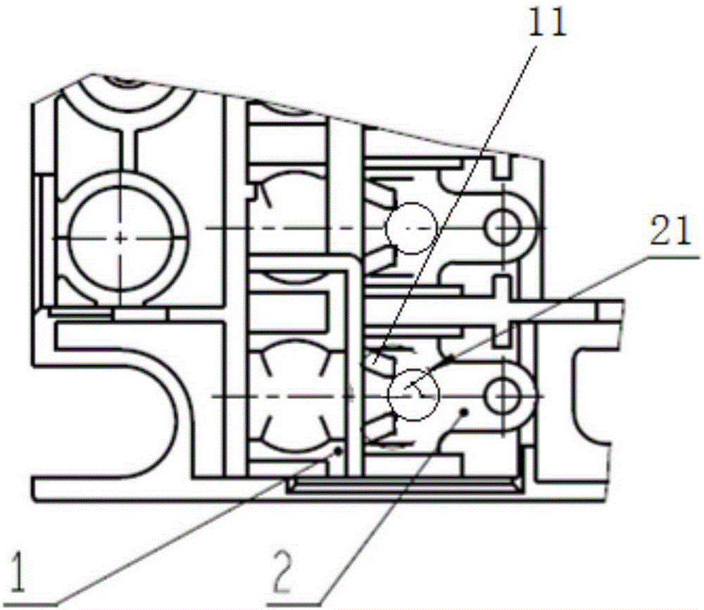
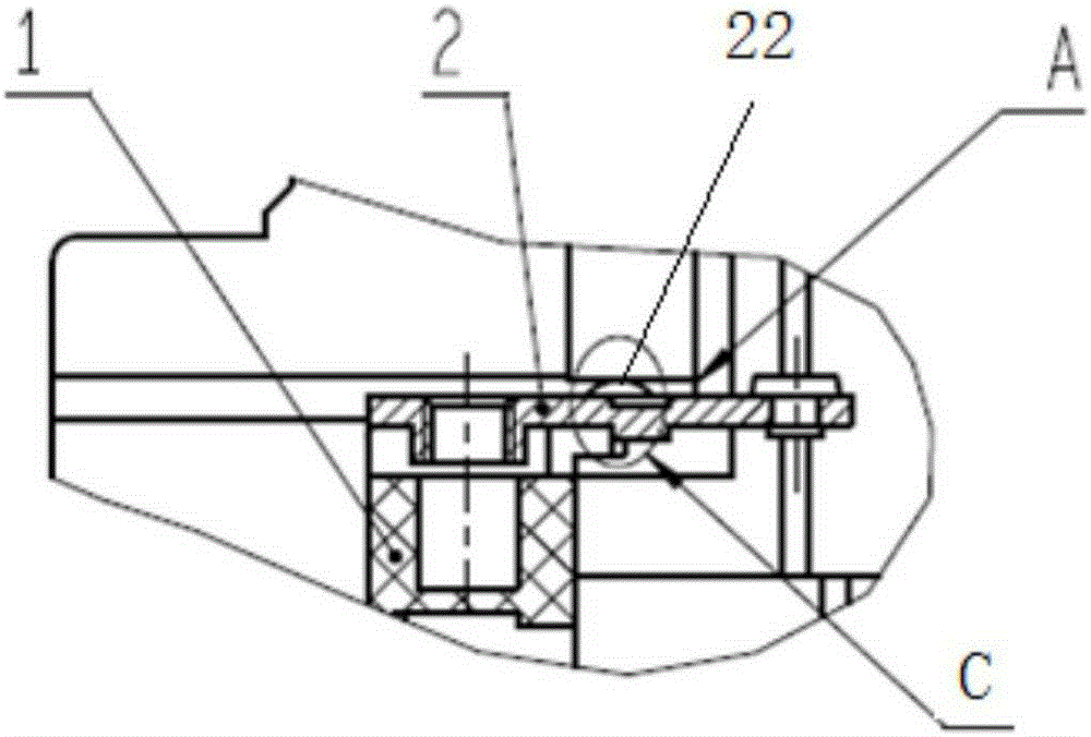
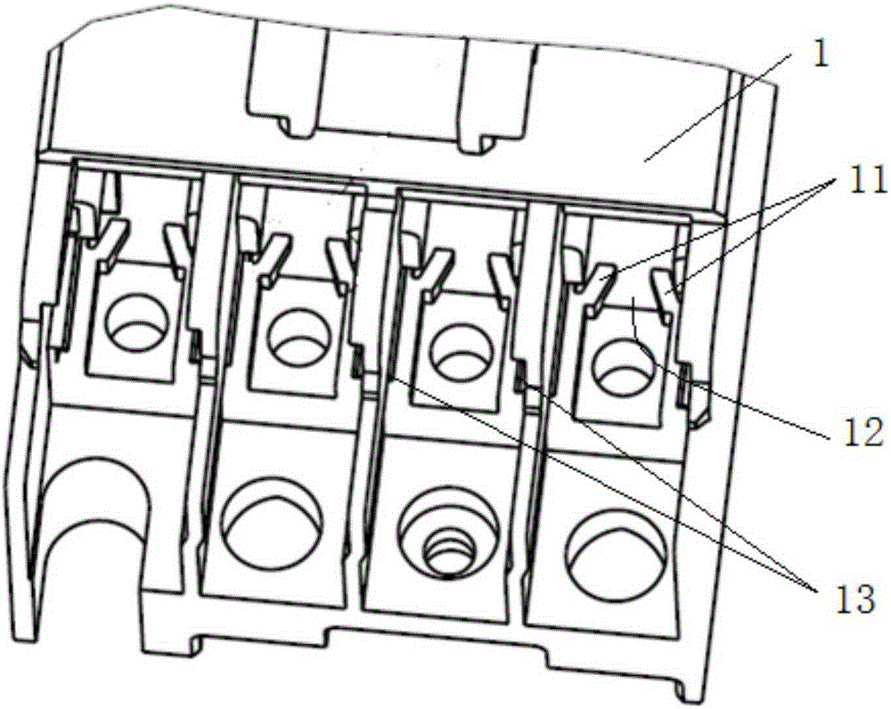
[0055] Such as figure 1 As shown, this embodiment provides a contact plate fixing structure, which includes a body shell 1 and a contact plate 2. The body shell 1 is formed with a slot 13 which restricts the contact plate 2 after being inserted into a certain position. The contact plate 2 cannot continue to advance along its insertion direction. The contact plate 2 is accurately positioned at the certain position of the slot 13 to ensure that the contact plate 2 is assembled to the required position. Yes, in this embodiment, the certain position is the top position of the contact plate 2 inserted into the slot 13 along the insertion direction of the contact plate 2 (ie fi...


PUM


Abstract

The invention provides a contact plate fixing structure which comprises a body and a contact plate. An inserting groove is formed in the body, and the inserting groove prevents the contact plate from continuing to advance in the inserting direction of the contact plate after the contact plate is inserted into a certain position. A boss is formed on the contact plate, the boss is provide with an arc edge, an elastic clamping groove allowing the boss to be inserted into is formed in the position, corresponding to the boss, of the body, when the contact plate is inserted into the certain position in the inserting groove and cannot continue to advance by being limited by the inserting groove, the elastic clamping groove and the boss form an inverted buckling and locking structure so that the contact plate cannot move in the direction opposite to the inserting direction of the contact plate, the contact plate can be located in the inserting direction of the contact plate and in the direction opposite to the inserting direction of the contact plate through the inverted buckling and locking structure and the inserting groove, the situation that the contact plate is crept and is loosened in the direction opposite to the inserting direction due to interference fit after being used for a long time is avoided, the inverted buckling and locking structure is formed and does not need new parts, and production cost cannot be increased.

Description

Technical field [0001] The invention relates to a contact plate fixing structure, belonging to the technical field of electrical switches. Background technique [0002] The contactor is an automatic control electrical appliance, which uses the current flowing through the coil to generate a magnetic field and close the contacts to control the load. The contactor usually consists of an electromagnetic system, a contact system, an arc extinguishing device, an insulating body and accessories. The contact system includes a static contact assembly and a moving contact. The moving contact is usually set in conjunction with the armature of the electromagnetic system. When the coil is energized, the armature drives the movable contact to cooperate with the corresponding static contact assembly, thereby turning on the load power. The static contact assembly is generally composed of a contact plate and a static contact. The static contact is fixed on the contact plate, and the contact plat...

Claims


Application Information

Patent Timeline
Patent Type & Authority Patents(China)
IPC IPC(8): H01H50/04
Inventor 蔡洪洲张红伟靳海富
Owner DELIXI ELECTRIC
Learn More