Electric connector for circuit board and electric connector assembly including the same

A technology for electrical connectors and circuit substrates, which is applied in the direction of connecting parts to protect grounding/shielding devices, components of connecting devices, circuits, etc., and can solve problems such as position deviation and instability, and achieve firm, reliable and maintained Effect

Inactive Publication Date: 2014-03-26
HIROSE ELECTRIC GROUP
View PDF0 Cites 2 Cited by
  • Summary
  • Abstract
  • Description
  • Claims
  • Application Information

AI Technical Summary

Problems solved by technology

Therefore, whenever an external force is applied, the position will shift, making it extremely unstable

Method used


Image

  • Electric connector for circuit board and electric connector assembly including the same
  • Electric connector for circuit board and electric connector assembly including the same
  • Electric connector for circuit board and electric connector assembly including the same

Examples


no. 1 approach >

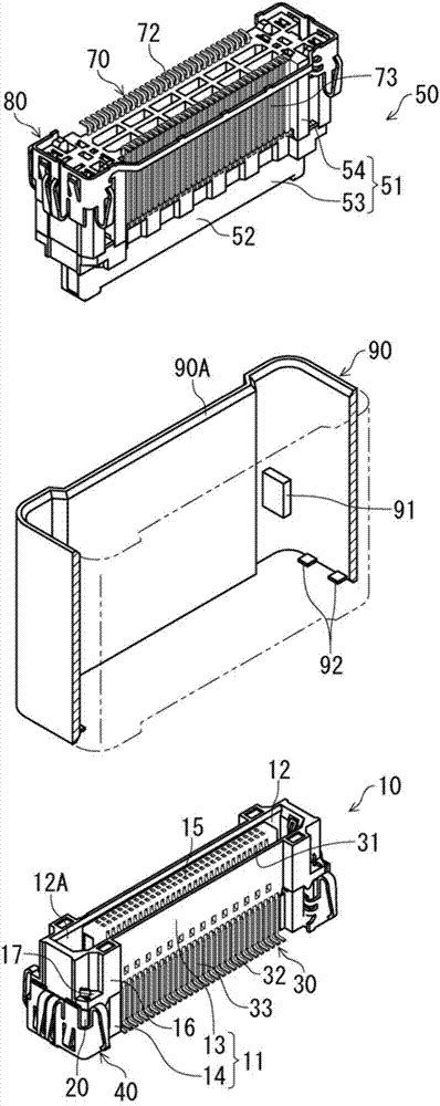
[0032] figure 1 An electrical connector assembly as a first embodiment obtained by holding a shield with two electrical connectors fitted to each other is shown in a state where the connector and the shield are separated.

[0033] exist figure 1In FIG. 2 , two connectors 10 , 50 shown positioned below and above are shown facing each other at positions before fitting separated from each other in the connector fitting direction (vertical direction). The connector 10 is a receptacle connector in which a fitting recess 12 is formed on a housing 11 made of an electrically insulating material. The plug connector of the fitting convex part 52 of the fitting concave part 12. The housing 11 of the socket-type connector 10 holds the terminal 30 and is equipped with a shield base 40 described later. A shield base 80.

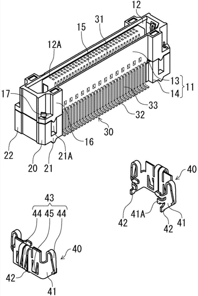
[0034] exist figure 2 In , the connector 10 is shown in a detached state before the shield base 40 is mounted on the housing 11 . From figure 1 , figure 2 It can...

no. 2 approach >

[0057] exist Figure 1 ~ Figure 4 In the first embodiment shown, the shielding bases 40, 80 attached to the electrical connectors 10, 50, respectively, are mounted with the shielding bases separated at both ends for each connector, but in this embodiment In an aspect, the shielding bases on the both end sides of the first embodiment are connected to each other by connecting tapes, and the shielding bases are attached to one connector as one component.

[0058] exist Figure 5 In the present embodiment shown, for the connectors 10 and 50, except for the shielding bases 40 and 80, the main body of the connector, that is, the housing and the terminals are all the same as those of the first embodiment, so the corresponding parts are labeled the same label and omit description.

[0059] Both shield bases 40 and 80 have the same form, and have the same mounted parts 41 and 81, holding parts 43 and 83, and soldering ground parts 42 and 82 as in the case of the first embodiment, but...

no. 3 approach >

[0065] The circuit boards P1 and P2 of the two connectors 10 and 50 of the electrical connector assemblies of the above-mentioned first and second embodiments are mounted in a positional relationship in which they are vertically parallel to each other, but the present invention can also be applied to this position. An application example where the relationship is a right angle is a so-called right-angle connector assembly.

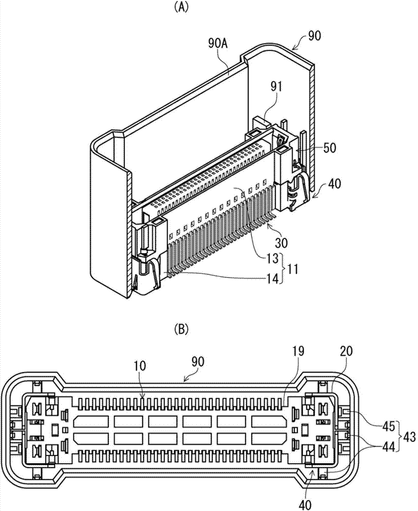
[0066] exist Figure 8 In the embodiment of the present invention shown in (A), the connector 10 arranged on one side of the circuit board P1 is a right-angle connector, and the lower surface of the connector 10 is mounted on the circuit board P1 , and the other side of the connection object is The connector 50 is fitted into a fitting recess (not shown) opened in the horizontal direction (right side in the drawing). The connector 50 itself is the same as the above-mentioned first embodiment, but in Figure 8 Among them, the circuit board P2 on which the...


PUM


Abstract

It is an object of the present invention to provide an electric connector for a circuit board and an electric connector assembly including the same, the electric connector having a simple configuration, being easily handleable, and including terminals having connecting portions with which a shield body is not in contact while being in use.An electric connector (10, 50, 210, 310, 350) for a circuit board, capable of being mounted on a surface of a circuit board, includes a housing (11, 51) that is capable of being covered by a tube-shaped or cover-shaped electrically conductive shield body (90, 190, 290, 390); terminals (30, 70) each having a solder connecting portion and positioned on a side of the housing (11, 51) that is to be attached to the circuit board, the solder connecting portion being capable of being soldered to the circuit board; and electrically conductive shield bases (40, 80) attached to an outer surface of the housing (11, 51). Each shield base (40, 80) includes an attached portion (41, 81), a solder ground portion (42, 82), and a holding portion (43, 83).

Description

technical field [0001] The present invention relates to an electrical connector for a circuit board and an electrical connector assembly having the electrical connector. Background technique [0002] Patent Document 1 discloses an electrical connector for a circuit board in which the periphery of an electrical connector mounted on a circuit board is covered with a cylindrical shield cover. In this Patent Document 1, the shield has a cylindrical shield body surrounding the connector and a contact protrusion protruding sideways from the edge of the opening of the shield body. When the electrical connectors are used in pairs, they are arranged in such a way that the surroundings of the mated connectors are surrounded by the above-mentioned shield body, and the above-mentioned contact protrusions are not soldered to the connection parts of the connector terminals, but only by being located on the connection contact with the connecting portion. In Patent Document 1, considering...

Claims


Application Information

Patent Timeline
Patent Type & Authority Applications(China)
IPC IPC(8): H01R13/648H01R12/51
CPCH01R12/73H01R13/6583
Inventor 涩谷和成
Owner HIROSE ELECTRIC GROUP
Why Eureka
Try Eureka