Method, device and system for measuring protection group switching time
A technology of switching time and protection group, applied in the field of communication, can solve the problems of easy misjudgment and poor operability of the switching time scheme, and achieve the effect of overcoming inaccurate measurement
- Summary
- Abstract
- Description
- Claims
- Application Information
AI Technical Summary
Problems solved by technology
Method used
Image
Examples
Embodiment approach 1
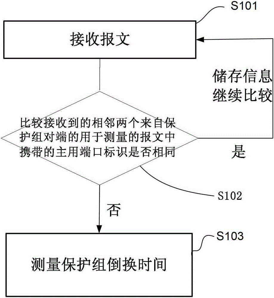
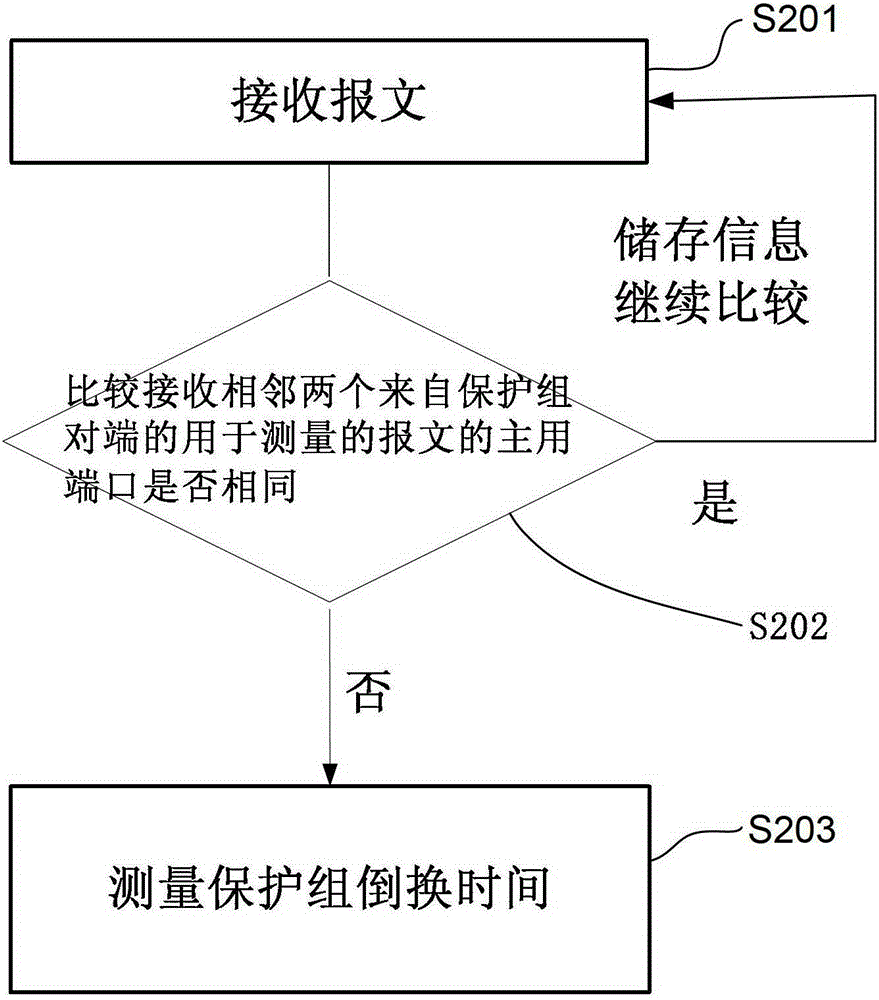
[0044] Embodiment 1: The embodiment of the present invention provides a protection group switching time measurement method, which can be applied to the networking structure of GPONTypeB or EPONTypeB, such as figure 1 and figure 2 As shown, the method includes:
[0045] The implementation principles of GPONTypeB and EPONTypeB protection mechanisms are similar, such as image 3 shown. These two protection groups use a 2:N optical splitter. There are two passive optical network (PON, Passive Optical Network) ports on the OLT connected to this 2:N optical splitter at the same time, and only one PON port is activated. state, the port corresponding to this PON is the active port, and the other PON port is in the standby state, and the port corresponding to it is the standby port. Of course, if the cost permits, there can be more than two ports on the OLT, one of which is active, and the rest are in standby state. In the embodiment of the present invention, a variety of messages...
Embodiment approach 2
[0056] Embodiment 2: The embodiment of the present invention provides a method for measuring the switching time of the protection group, such as figure 1 and figure 2 shown.
[0057] like Figure 4 As shown in , the Ethernet port protection group can be used for link protection between the aggregation device and the access device. Both the aggregation device and the access device have two ports, and both ports of the device are enabled, but only the active port is in the active state, and the other port is in the standby state. In some cases, there may be more than one standby port in the protection group, and this method is also applicable. In the embodiment of the present invention, a variety of messages or messages that can carry port identifiers can be used. The following only takes Ethernet messages as an example. The messages used to measure the switching time of the protection group can be ordinary messages or special messages. Packet used to measure the switching ...
Embodiment approach 3
[0065] Embodiment 3: The embodiment of the present invention provides a method for measuring protection group switching time, which can be applied to a network structure such as GPONTypeC or EPONTypeD, such as figure 1 , figure 2 shown.
[0066] The GPONTypeC protection group uses a 2:N optical splitter, and the EPONTypeD protection group uses a 1:N optical splitter, but the implementation principles of the two protection mechanisms are similar. Figure 5 shown. The two ports of the OLT are respectively connected to two optical splitters, and the two ports of each ONU or ONT are also respectively connected to the two optical splitters. Both OLT and ONU have only one PON port in the active state, which is the active port, and the other PON port is in the standby state, which is the standby port. In some cases, there may be more than one standby port in the protection group, and this method is also applicable. In the embodiment of the present invention, a variety of message...
PUM
 Abstract
Description
Claims
Application Information
 - R&D
- Intellectual Property
- Life Sciences
- Materials
- Tech Scout
- Unparalleled Data Quality
- Higher Quality Content
- 60% Fewer Hallucinations
Browse by: Latest US Patents, China's latest patents, Technical Efficacy Thesaurus, Application Domain, Technology Topic, Popular Technical Reports.
© 2025 PatSnap. All rights reserved.Legal|Privacy policy|Modern Slavery Act Transparency Statement|Sitemap|About US| Contact US: help@patsnap.com


