Azimuth measurement device, antenna and azimuth measurement system and method

A technology of measuring device and measuring method, which is applied in the field of communication, and can solve problems such as high cost, bending deformation, difficulty in accurately measuring the azimuth angle of antenna installation, etc.

Pending Publication Date: 2017-12-15
COMBA TELECOM TECH (GUANGZHOU) CO LTD
View PDF4 Cites 4 Cited by
  • Summary
  • Abstract
  • Description
  • Claims
  • Application Information

AI Technical Summary

Problems solved by technology

However, the base station antenna is surrounded by a ferromagnetic environment and is always disturbed by electromagnetic waves. It is difficult to accurately measure the azimuth angle of the antenna installation by using the existing technology.
[0005] Generally speaking, the geomagnetism is evenly distributed and points to the true north; when subjected to ferromagnetic interference, the local geomagnetic lines will bend and deform, resulting in uneven distribution of geomagnetic density around the measuring device and inaccurate static azimuth measurement
[0006] In terms of the measurement of azimuth angle based on the principle of geomagnetic induction, the industry has proposed the application of plane circular motion sampling correction compensation, but most of them are based on manual operation correction compensation, which is difficult to achieve in engineering applications, and the operation is extremely inconvenient
At the same time, the plane circular motion sampling is limited to effective measurement only when the object is installed horizontally; in the field of antenna application, since the antenna is installed with a downtilt angle, when the measuring device and the antenna are installed together, it will also produce downslope. Inclination, that is, the measurement plane and the calibration plane are not on the same plane, resulting in inaccurate measured azimuth angles
[0007] In addition, the industry also has azimuth measurement technology based on the GPS principle, but because of its high cost and the fact that the azimuth measurement accuracy is greatly affected by the weather, it cannot be effectively applied

Method used


Image

  • Azimuth measurement device, antenna and azimuth measurement system and method
  • Azimuth measurement device, antenna and azimuth measurement system and method

Examples


Embodiment Construction

[0032] Embodiments of the present invention are described in detail below, examples of which are shown in the drawings, wherein the same or similar reference numerals designate the same or similar elements or elements having the same or similar functions throughout. The embodiments described below by referring to the figures are exemplary only for explaining the present invention and should not be construed as limiting the present invention.

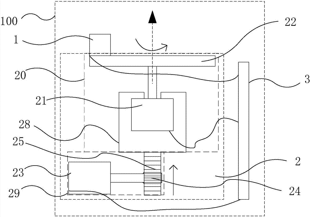
[0033] figure 1 The azimuth measuring device 100 of the present invention is shown, including an induction device 1 for detecting surrounding geomagnetic signals, a drive device 2 for driving the induction device 1 to perform a spiral motion, and controlling the operation of the drive device 2 and controlling the induction device 1 Geomagnetic signal processing for detection and measurement main board 3 for internal correction and compensation.

[0034] The induction device 1 is a magnetic sensor 1, which includes a first sensor (not sh...


PUM


Abstract

The invention provides an azimuth measurement device. The azimuth measurement device comprises an induction device for detecting the geomagnetic distribution situation in the periphery of a measurement device, a driving device and a measurement main board. A control instruction output by the measurement main board controls the driving device to drive the induction device to carry out spiral movement, the measurement main board receives geomagnetic signals detected by the induction device and then carries out correction and compensation so as to eliminate the influence produced by the environment around the measurement device on the azimuth measurement. Compared with the existing device, the azimuth measurement device has the advantages of high measurement precision and low cost. The invention also relates to an antenna with the azimuth measurement device, an azimuth measurement system and an azimuth measurement method for the azimuth measurement system.

Description

technical field [0001] The present invention relates to the communication field, in particular, the present invention relates to a device and a method for measuring the azimuth angle of base station antenna installation by using a geomagnetic induction device on the base station antenna. Background technique [0002] Azimuth angle, also known as heading angle, is an important parameter for navigation and attitude measurement, and plays an important role in the field of motion control or engineering geography design. [0003] In communications, an antenna is a device used to transmit and receive radio signals. Since the radiation surface of the antenna is oriented in a fixed direction, in order to achieve the best coverage effect of the antenna, the antenna is usually designed and installed in a specified direction (that is, the preset azimuth) when the base station is built. The field needs to measure the azimuth angle of the antenna installation. [0004] In practical app...

Claims


Application Information

Patent Timeline
Patent Type & Authority Applications(China)
IPC IPC(8): G01C1/00
CPCG01C1/00
Inventor 马泽峰潘培锋宋拟邓宏俊
Owner COMBA TELECOM TECH (GUANGZHOU) CO LTD
Why Eureka
Try Eureka