Backlight driving circuit and TV

A backlight drive circuit and drive controller technology, applied in the field of circuits, can solve the problems of complex safety protection methods and high voltage, and achieve the effects of improving the appearance, reducing the insulation level, and avoiding current inconsistencies

Active Publication Date: 2017-02-08
HISENSE VISUAL TECH CO LTD
View PDF2 Cites 0 Cited by
  • Summary
  • Abstract
  • Description
  • Claims
  • Application Information

AI Technical Summary

Problems solved by technology

[0005] The present invention provides a backlight driving circuit and a TV set, which are used to solve the problem that the existing backlight module requires a relatively high voltage and thus lead to complicated safety protection methods, so as to simplify the safety protection method of the backlight module

Method used


Image

  • Backlight driving circuit and TV
  • Backlight driving circuit and TV
  • Backlight driving circuit and TV

Examples


Embodiment 1

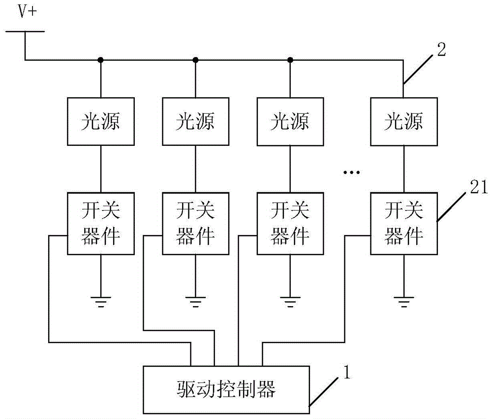
[0035] figure 1 It is a schematic structural diagram of a backlight driving circuit provided by Embodiment 1 of the present invention. The backlight driving circuit can be applied in a liquid crystal television, and specifically can be arranged on a power supply board, or can be integrated and arranged on a main board. Such as figure 1 As shown, the backlight driving circuit may include a driving controller 1 , a switching device 21 and at least two light bars 2 .

[0036] Wherein, each light bar 2 is connected in parallel, and at least one light bar 2 is connected with a switching device 21 in series. The pulse signal output terminal of the driving controller 1 is connected to the control terminal of the switching device 21, and the current of each light bar 2 is controlled by pulse width modulation, so that the current amplitude of each light bar 2 remains consistent.

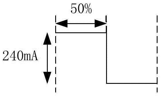
[0037] Specifically, the pulse signal output terminal of the drive controller 1 outputs a pulse signal ...

Embodiment 2

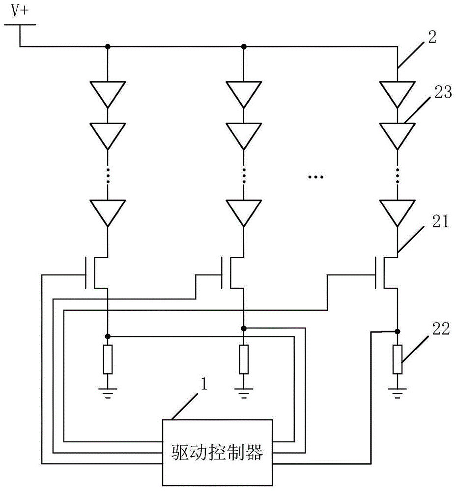
[0043] For the light bar 2 and the drive controller 1 in the above technical solution, those skilled in the art can design a variety of circuit structures to realize. This embodiment provides a specific structure that can be realized, which can be referred to figure 2 , figure 2 It is a schematic structural diagram of a backlight driving circuit provided by Embodiment 2 of the present invention.

[0044] The light bar 2 may include a resistor 22 and at least two light sources 23 connected in series, wherein the anodes of the at least two light sources 23 connected in series receive the driving voltage, and the cathodes of the at least two light sources 23 connected in series are connected to the first connection end of the resistor 22, The second connection of the resistor 22 is grounded. Taking two light sources 23 as an example, the negative pole of the first light source 23 is connected to the positive pole of the second light source 23 to form a light string, and the po...

Embodiment 3

[0055] The mainboard and power supply board of the existing TV are usually installed on the backboard, wherein the power supply board is provided with a power drive circuit and a backlight drive circuit, which are respectively used to supply power to the mainboard and drive the backlight module. It is necessary to keep a certain safety distance, so that the size of the TV in the thickness direction is relatively large.

[0056] This embodiment provides a new type of TV. Instead of using a power board, the backlight drive circuit in the power board is integrated into the main board, and the power drive circuit is set in the form of an external power adapter, which can reduce the size of the circuit board. Occupies more space, thereby reducing the thickness of the TV.

[0057] Figure 5 It is a schematic structural diagram of a TV set provided by Embodiment 3 of the present invention. Such as Figure 5 As shown, the TV set provided in this embodiment includes a main board, an...


PUM


Abstract

The invention provides a backlight drive circuit and a television. The backlight drive circuit comprises at least two lamp strips, a drive controller and a switching device. The lamp strips are connected in parallel. At least one lamp strip is serially connected with the switching device. The pulse signal output end of the drive controller is connected with the control end of the switching device. The current of the lamp strips is controlled by means of pulse width modulation, so that the current amplitudes of the lamp strips are kept consistent. The backlight drive circuit and the television have the advantages that the problem that the need of the existing backlight module for high voltage causes complexity in safety protection modes can be solved and the safety protection modes of backlight modules are simplified.

Description

technical field [0001] The invention relates to circuit technology, in particular to a backlight driving circuit and a TV set. Background technique [0002] The backlight light sources of LCD TVs are usually divided into Cold Cathode Fluorescent Lamp (CCFL for short), Light-Emitting Diode (LED for short), and Hot Cathode Fluorescent Lamp (HCFL for short). Wherein, the LCD TV whose backlight light source is LED (referred to as LED LCD TV) usually includes a main board and a power board, and the main board and the power board are arranged on the back board, wherein, the power board is provided with a power driving circuit and an LED driving circuit. [0003] The LED driving circuit of the existing LCD TV usually includes a backlight module composed of a plurality of LED light bars, the LEDs in each LED light bar are connected in series, and the LED light bars are also connected in series. Its control method adopts LED constant current control. In order to keep each LED with ...

Claims


Application Information

Patent Timeline
Patent Type & Authority Patents(China)
IPC IPC(8): H05B37/02H04N13/00
Inventor 韩文涛徐爱臣
Owner HISENSE VISUAL TECH CO LTD
Why Eureka
Try Eureka