A driving circuit of an organic light emitting display device

A technology of light-emitting display devices and driving circuits, applied in static indicators, instruments, etc., can solve problems such as uneven light emission, achieve the effect of balancing the capacitance value, improving the capacitance value, and avoiding the inconsistency of the current

Inactive Publication Date: 2012-02-01
SICHUAN CCO DISPLAY TECH
View PDF0 Cites 0 Cited by
  • Summary
  • Abstract
  • Description
  • Claims
  • Application Information

AI Technical Summary

Problems solved by technology

[0006] The purpose of the present invention is to overcome the shortcomings of uneven light emission between different pixel circuits of the existing OLED drive circuit

Method used


Image

  • A driving circuit of an organic light emitting display device
  • A driving circuit of an organic light emitting display device
  • A driving circuit of an organic light emitting display device

Examples


Embodiment Construction

[0022] The present invention will be further described below in conjunction with the accompanying drawings and specific embodiments.

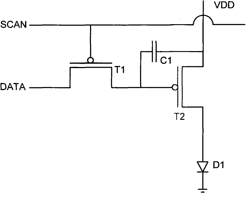
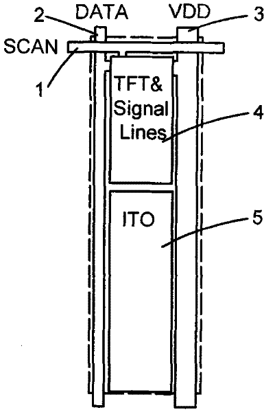
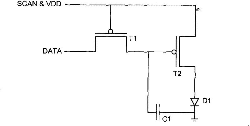
[0023] Such as Figure 6 , Figure 7 and Figure 8 As shown, the present invention is composed of M×N (M, N are natural numbers, M and N are both taken as 3 in this embodiment) light-emitting pixel units are arranged and combined according to a matrix structure, and each light-emitting pixel unit includes a pixel circuit and a light-emitting diode D1, the pixel circuit includes two transistors, a switching transistor T1 and a driving transistor T2, and a holding capacitor C1, and the pixel circuit is respectively connected to a data line 2 (DATA) for transmitting data signals for transmission scanning The scan line 1 (SCAN) of the selection signal is used to provide the power supply voltage line 3 (VDD) of the driving power, which is used to connect the organic electroluminescent diode D1 that emits light according to the corresponding scan s...


PUM


Abstract

The invention relates to a driving circuit of an organic light-emitting display device, which is formed by arraying and combining multiple rows of light-emitting pixel units and multiple arrays of light-emitting pixel units according to a matrix structure, wherein each light-emitting pixel unit comprises a pixel circuit and a light-emitting diode; and the pixel circuit comprises two transistors and a maintenance capacitor. The driving circuit is characterized in that the maintenance capacitors of the light-emitting pixel units of the same row are connected by a metal wire of the maintenance capacitor and are connected to the grounding end of the light-emitting diode at the last light-emitting pixel unit of the same row. The driving circuit has the advantage that the inconsistent current caused by the own difference of the maintenance capacitors among the light-emitting pixel units in the light-emitting diodes is avoided, and has the most obvious advantage that the problem of asymmetrical brightness among single pixels due to the different maintenance capacitors is solved.

Description

technical field [0001] The invention belongs to the field of plane display technology, in particular to a driving circuit of an organic light-emitting display device (OLED, Organic Light-Emitting Display). Background technique [0002] Generally, an organic light-emitting display is composed of N×M (N rows, M columns, N and M are natural numbers) light-emitting pixel units arranged in a matrix structure, and each light-emitting pixel unit contains an organic light-emitting diode (Organic Light-Emitting Diode) and a corresponding pixel circuit. Such as figure 1 As shown, the existing pixel circuit includes two transistors and a capacitor, wherein the gate and source of the switching transistor T1 are respectively connected to the scanning line (SCAN) and the data line (DATA), and the drain of the switching transistor T1 is connected to the driving The gate of the transistor T2 is connected; the source of the driving transistor T2 is connected to the power supply voltage lin...

Claims


Application Information

Patent Timeline
Patent Type & Authority Patents(China)
IPC IPC(8): G09G3/32G09G3/3208
Inventor 金正学洪宣杓
Owner SICHUAN CCO DISPLAY TECH
Why Eureka
Try Eureka