Liquid crystal display device having improved touch screen

Inactive Publication Date: 2007-02-22
SAMSUNG ELECTRONICS CO LTD
View PDF3 Cites 133 Cited by
  • Summary
  • Abstract
  • Description
  • Claims
  • Application Information

AI Technical Summary

Benefits of technology

[0007] When the capacitance of the variable capacitors increases, the amount of current flowing through the first switching element decreases in proportion to the sensing data signal

Problems solved by technology

However, the manufacturing cost of such a liquid crystal display increases due to the touch screen panel, and the yi

Method used


Image

  • Liquid crystal display device having improved touch screen
  • Liquid crystal display device having improved touch screen
  • Liquid crystal display device having improved touch screen

Examples


Example

[0020] The present invention will now be described more fully hereinafter with reference to the accompanying drawings, in which preferred embodiments of the invention are shown.

[0021] In the drawings, the thickness of layers, films, panels, regions, etc., are exaggerated for clarity. Like reference numerals designate like elements throughout the specification. It will be understood that when an element such as a layer, film, region or substrate is referred to as being “on” another element, it can be directly on the other element or intervening elements may also be present. In contrast, when an element is referred to as being “directly on” another element, there are no intervening elements present.

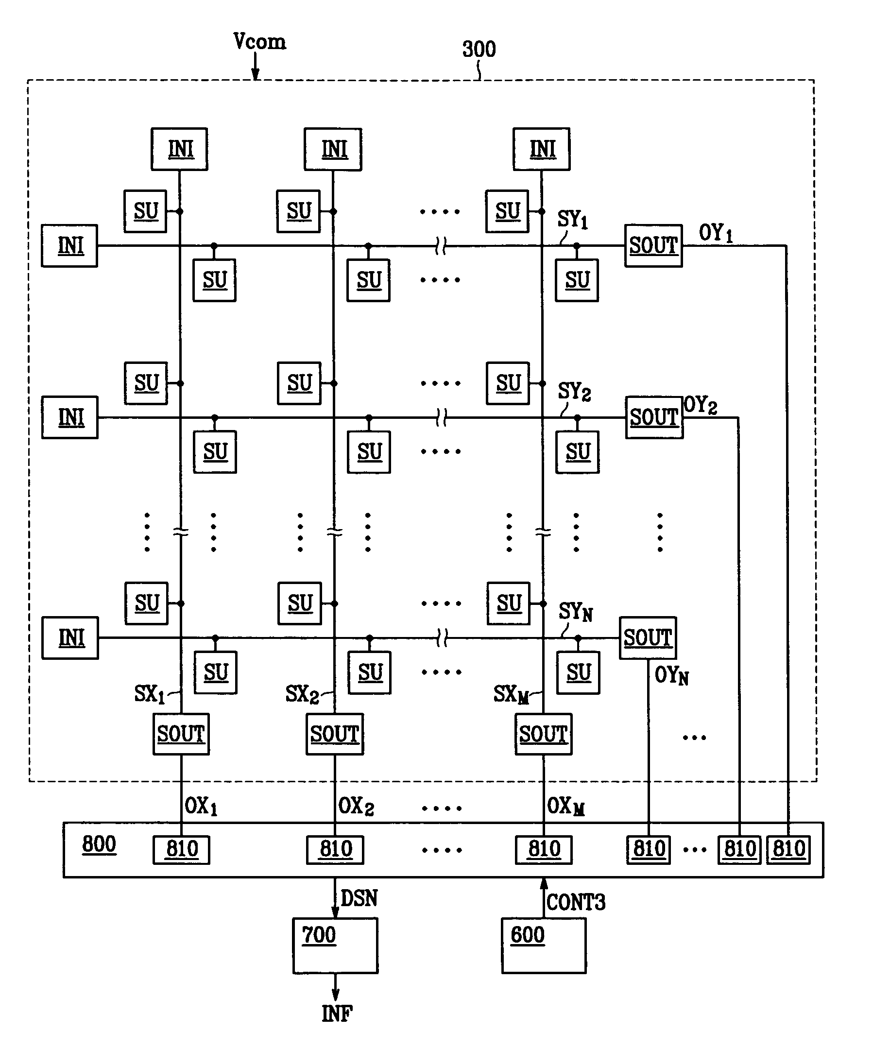
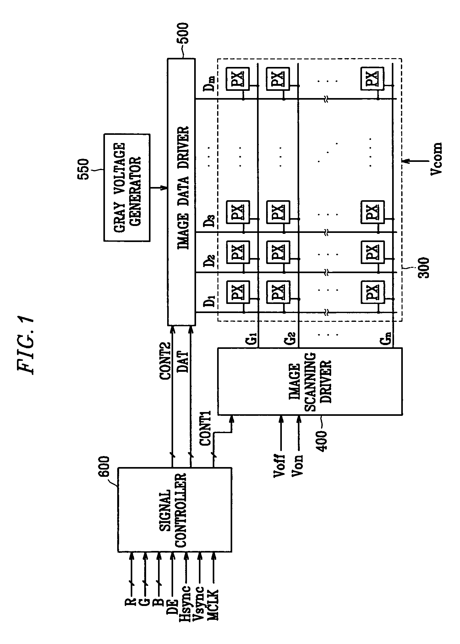
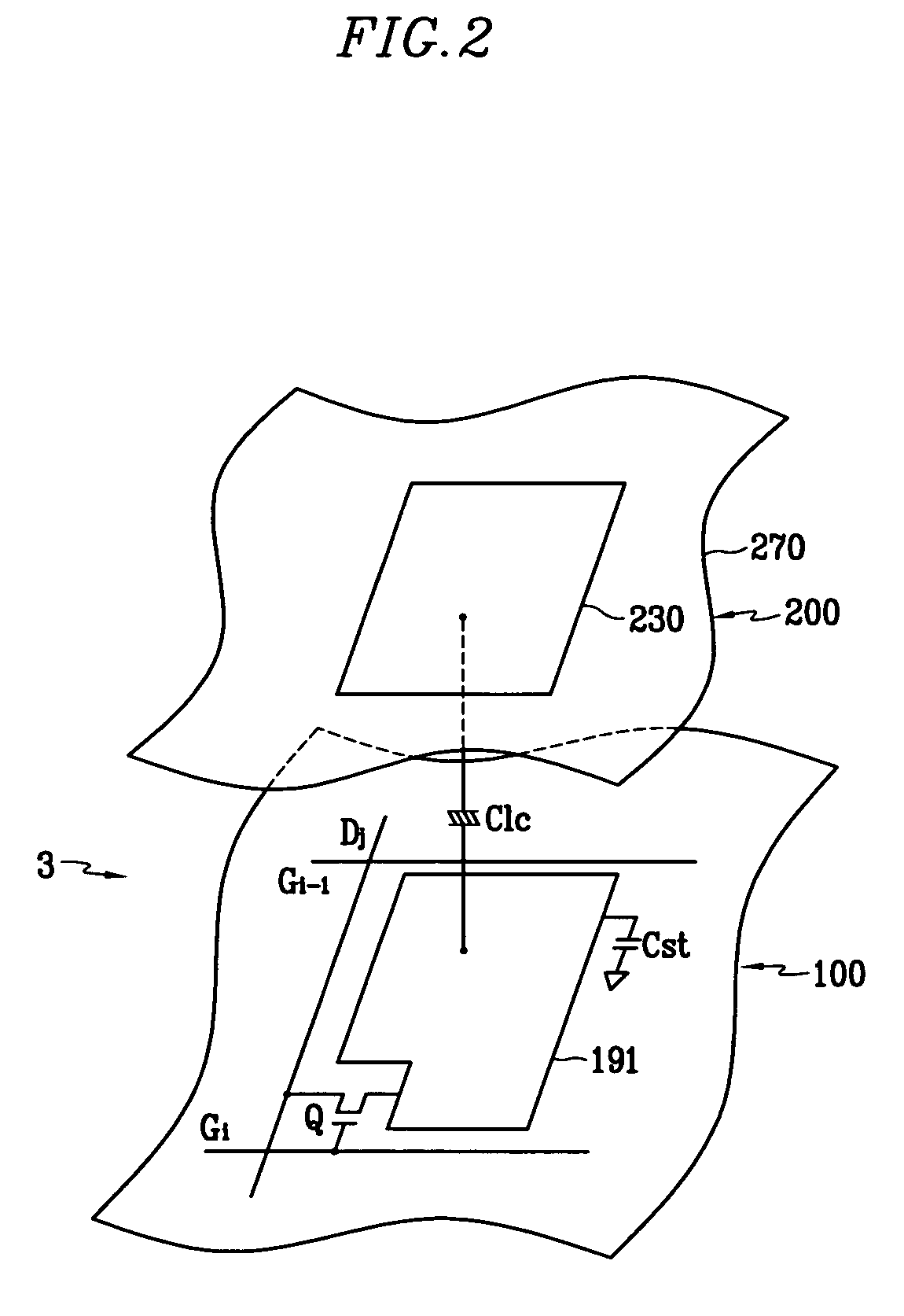
[0022] A liquid crystal display according to an exemplary embodiment of the present invention will now be described in detail with reference to FIG. 1 to FIG. 5. FIG. 1 is a block diagram of a liquid crystal display according to an exemplary embodiment of the present invention, in which t...


PUM


Abstract

A liquid crystal display having a touch screen includes a plurality of sensing data lines formed on a display panel, a plurality of variable capacitors connected to the sensing data lines and having capacitance that varies with a pressure, a plurality of reference capacitors connected to the sensing data lines, and a plurality of sensing signal output units each connected to the sensing data lines for generating output signals on the basis of sensing data signals that flow through the sensing data lines. The sensing signal output units change the amount of current based on the sensing data signals to reduce current corresponding to the output signals.

Description

CROSS-REFERENCE TO RELATED APPLICATION [0001] This application claims priority to and the benefit of Korean Patent Application No. 10-2005-0105430 filed in the Korean Intellectual Property Office on Nov. 4, 2005, the entire contents of which are incorporated herein by reference. FIELD OF THE INVENTION [0002] The present invention relates to a liquid crystal display having a touch screen. DESCRIPTION OF THE RELATED ART [0003] A liquid crystal display (LCD), is representative of display devices that include two display panels respectively having a matrix of pixel electrodes and a common electrode with a liquid crystal layer having dielectric anisotropy interposed between the two panels. The pixel electrodes are connected to switching elements such as a thin film transistor (TFT). A data voltage is sequentially supplied to the pixel electrodes one row at a time. The common electrode is formed on the entire surface of one display panel and receives a common voltage. A pixel electrode, t...

Claims


Application Information

Patent Timeline
IPC IPC(8): G09G5/00
CPCG06F3/0412G09G3/3648G06F3/0447G02F1/133
Inventor LEE, JOO-HYUNGPAK, SANG-JINUH, KEE-HANJEONG, DONG-JIN
Owner SAMSUNG ELECTRONICS CO LTD
Why Eureka
Try Eureka