Emergency LED lamp

A technology of LED lamps and LED modules, which is applied in the direction of electric lamp circuit layout, lighting devices, light sources, etc., can solve the problems of single function and inconvenient use of LED lamps, and achieve the effects of convenient use, avoiding switching operations, and ensuring safe use

Active Publication Date: 2014-03-26
许荣林 +1
View PDF5 Cites 8 Cited by
  • Summary
  • Abstract
  • Description
  • Claims
  • Application Information

AI Technical Summary

Problems solved by technology

[0003] In order to solve the problem of single function and inconvenient use of LED lamps in the prior art, the present invention provides an emergency LED lamp that is easy to install, easy to operate, and can save energy.

Method used


Image

  • Emergency LED lamp
  • Emergency LED lamp
  • Emergency LED lamp

Examples


Embodiment 1

[0029] Embodiment 1 of the present invention provides an emergency LED light, such as figure 1 shown, including:

[0030] A light-emitting LED module 101, used to emit light when a power supply is connected;

[0031] In this embodiment, the light-emitting LED module 101 can include one LED or multiple LEDs. If multiple LEDs are included, the multiple LEDs can be connected in parallel, in series or in parallel. Preferably, this In the embodiment, the series connection is adopted;

[0032] An external control switch 102 is connected to an external power supply for controlling the on and off of the transformer circuit 103;

[0033] Preferably, the external control switch 102 in this embodiment can use an existing lamp control switch, such as a pull cord or a toggle switch;

[0034] Transformer circuit 103, connected with external control switch 102, external power supply, light-emitting LED module 101 and control unit 104, is used to perform voltage transformation processing w...

Embodiment 2

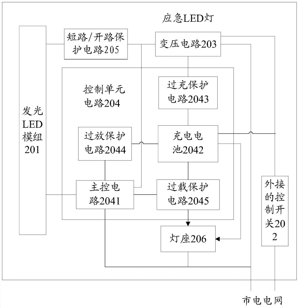
[0041] Embodiment 2 of the present invention provides an emergency LED lamp, which has two light sources and realizes the functions of ordinary lighting, emergency lighting and outdoor lighting, such as figure 2shown, including:

[0042] A light-emitting LED module 201, used to emit light when a power supply is connected;

[0043] In this embodiment, the light-emitting LED module 201 includes 5 LEDs, which are connected in series;

[0044] An external control switch 202 is connected to an external power supply and is used to control the on and off of the transformer circuit 203;

[0045] Specifically, the external control switch 202 in this embodiment can use a pull cord or a toggle switch;

[0046] Transformer circuit 203 is connected with external control switch 202, external power supply, light-emitting LED module 201 and control unit 204, and is used for performing voltage transformation processing when the external power supply provides power and external control switc...


PUM


Abstract

The invention discloses an emergency LED lamp. The emergency LED lamp comprises a LED module for emitting light when being connected with a power supply, an external control switch used for controlling on-off of a voltage transforming circuit, the voltage transforming circuit and a control unit circuit. The voltage transforming circuit is used for transforming the voltage when the external control switch is conducted and providing a power supply for the LED module. The control unit circuit is used for automatically switching the power supply and controlling the LED module to emit the light. The control unit circuit comprises a main control circuit and a rechargeable battery. When the municipal grid provides electricity and the control switch is conducted, the LED module emits light and the rechargeable battery is charged. When the municipal grid does not provide electricity and the control switch is conducted, a control circuit controls the rechargeable battery to provide power for the LED module and turning on the LED module. Thus, no matte whether the external power supply is on or off, the same control switch can be used for turning on or turning off the LED module.

Description

technical field [0001] The invention relates to the technical field of LED lighting, in particular to an emergency LED lamp with convenient installation, simple operation and energy saving. Background technique [0002] Due to the advantages of energy saving, environmental protection, high luminous efficiency, and long life, LED lights have been rapidly applied to various fields. Based on the AC / DC dual-purpose lamps currently on the market, it is necessary to set an AC / DC conversion switch and a switch to control the light on and off on the lamp, which is convenient to use, especially when the lamp is installed at a high place. Inconvenient; and the existing LED lighting lamp has a single function and cannot realize the multi-purpose function of one lamp. In the prior art, when many fire emergency lights are powered off during the day, the emergency lights will automatically turn on. If the power fails for a few hours, the battery power in the lights will be exhausted. Th...

Claims


Application Information

Patent Timeline
Patent Type & Authority Applications(China)
IPC IPC(8): H05B37/02
Inventor 许荣林
Owner 许荣林
Why Eureka
Try Eureka