Sleeve shaft type stirring mud scraper

A mud scraper and sleeve shaft technology, which is applied in the sedimentation tank, the feeding/discharging device of the sedimentation tank, chemical instruments and methods, etc. The effect of reducing power consumption, reducing floor space and facilitating maintenance

Active Publication Date: 2014-04-02
JIANGSU YIHUAN GROUP
View PDF6 Cites 1 Cited by
  • Summary
  • Abstract
  • Description
  • Claims
  • Application Information

AI Technical Summary

Problems solved by technology

Its technical solution adopts a conventional split-type independent structure. Even if the purpose of convenient maintenance can be achieved as the inventor said, the transmission device of the mud scraper is a structure in which gears and pin gears are connected by transmission, and its structure is complicated. Because it works at the bottom of the pool, the gears and pin gears are subject to long-term corrosion and are easily damaged. Once damaged, they need to be taken out as a whole for maintenance. In fact, the purpose of easy maintenance cannot be achieved and needs to be improved.

Method used


Image

  • Sleeve shaft type stirring mud scraper
  • Sleeve shaft type stirring mud scraper

Examples


Embodiment Construction

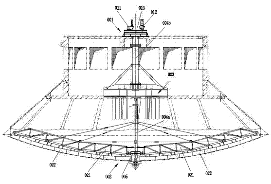
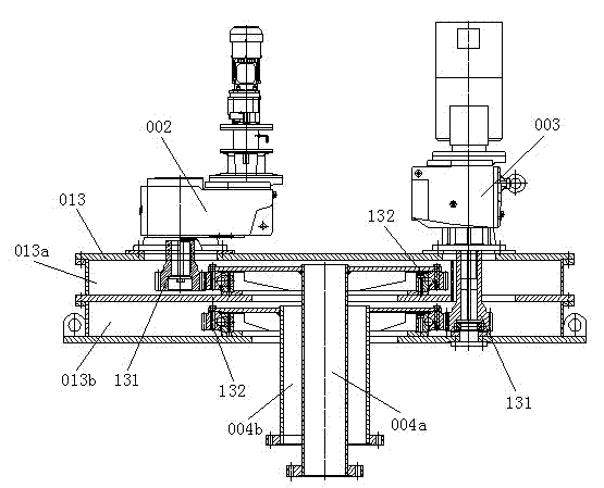
[0011] A shaft-type stirring and scraping machine, the stirring and scraping machine is arranged in the clarification tank, including a driving device 001, a mud scraping device 002 connected to the driving device 001, and a stirring device 003, and the driving device 001 is a central drive mechanism, the central drive mechanism includes a mud scraping reducer 011, a stirring reducer 012, and a reducer case 013, and the reducer case 013 includes a transmission pinion 131 in the reduction case 013 and a passive bull gear meshed with the transmission pinion 131 for transmission 132, the reduction box 013 is set as upper and lower chambers (013a, 013b), and the upper and lower chambers (013a, 013b) are equipped with intermeshing large and small gears (131, 132), and the mud scraping decelerates The outlet shafts of the machine 011 and the stirring reducer 012 pass through the holes opened on the reducer case 013 to connect with the holes on the pinion 131 in the upper and lower tw...


PUM


Abstract

The invention discloses a sleeve shaft type stirring mud scraper. The stirring mud scraper is arranged in a clarification tank and comprises a driving device and a mud scraping device and a stirring device connected with the driving device, wherein the driving device is a central driving mechanism, the central driving mechanism comprises a mud scraping speed reducer, a stirring speed reducer and a speed reducer box, the speed reducer box comprises a transmission pinion in the speed reducer box and a driven rack wheel in engaged transmission with the transmission pinion, the speed reducer box is arranged to be provided with an upper-layer chamber and a lower-layer chamber, mutually engaged pinions and rack wheels are arranged in the upper-layer chamber and the lower-layer chamber, output shafts of the mud scraping speed reducer and the stirring speed reducer are connected with holes in the pinions in the upper-layer chamber and lower-layer chamber after penetrating through holes formed in the speed reducer box, the centers of the driven rack wheels in the upper-layer chamber and the lower-layers chamber are respectively connected with transmission shafts through sleeve shafts, the transmission shaft on the driven rack wheel of the upper-layer chamber is coaxially sleeved in the transmission shaft on the driven rack wheel of the lower-layer chamber, the two transmission shafts are respectively connected with the mud scraping device and the stirring device after penetrating through a central axle hole formed in the bottom end of the speed reducer box, the structure of the driving device is greatly simplified and the occupation area is reduced.

Description

technical field [0001] The invention relates to the technical field of water treatment clarification tanks. Background technique [0002] The mud scraper and mud scraper in the clarification tank of the prior art generally include a mud scraper and a mixer, but although they are arranged in one pool, they are independent structures, and a reducer and a transmission device need to be installed separately, which not only has a complex structure but also costs a lot. High, in order to solve this problem, there is also a coaxial arrangement of the drive shafts of the two devices in the prior art, but since different reducers and motors need to be configured separately, the structure is more complicated when the site is arranged, and the occupied area is limited. Larger, the energy consumption is also the same as that of the independent setting, and the effect of reducing energy consumption has not been achieved, and needs to be improved. [0003] Furthermore, the Chinese invent...

Claims


Application Information

Patent Timeline
Patent Type & Authority Applications(China)
IPC IPC(8): B01D21/24B01D21/04B01D21/18
Inventor 朱苏彤顾强李巍刘燕婷闵俊杰
Owner JIANGSU YIHUAN GROUP
Why Eureka
Try Eureka