
A die forging forming method of mounting seat

A mounting seat and die forging technology, which is applied in metal processing equipment and other directions, can solve the problem that the blank is not easy to locate the lateral force, etc., achieve the effect of small plastic deformation, balance the lateral force of die forging, and ensure the size of the profile

Active Publication Date: 2016-05-25
WUXI TURBINE BLADE
View PDF6 Cites 0 Cited by
  • Summary
  • Abstract
  • Description
  • Claims
  • Application Information

AI Technical Summary

Problems solved by technology

[0003] In view of the above problems, the present invention provides a die forging forming method of the mounting seat, which can effectively solve the problems of difficult positioning of the blank in the forging die and lateral force during die forging in the existing die forging process

Method used


Image

  • A die forging forming method of mounting seat
  • A die forging forming method of mounting seat
  • A die forging forming method of mounting seat

Examples


Embodiment Construction

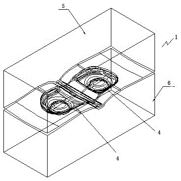
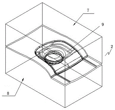
[0012] A die forging forming method of a mounting seat, which adopts a process route of pre-forging, final forging, and hot shaping. Firstly, a pre-forging die 1 is used to pre-forge a blank, and then a final forging die 2 is used to pre-forge the pre-forged pre-formed The forging is final forged, and finally the forging after final forging is thermally shaped; the pre-forging die 1 has a structure of one die and two cavities, and the pre-forging die 1 has two forming cavities 4, and the two forming cavities 4 mirror Symmetrical connection; after the pre-forging is completed, the pre-forging is divided into two mounting seat pre-forgings, and then the final forging die is used to perform final forging on the two mounting seat pre-forgings, and finally the two forgings after final forging are heat-treated plastic surgery. The final forging die 2 is a one-mold-one-cavity structure. figure 2 Among them, 5 is the upper die of the pre-forging die, and 6 is the lower die of the pr...


PUM


Abstract

The invention provides a die forging molding method for a mounting seat, which can effectively solve the problems of difficult positioning of a blank in a forging die and lateral force during die forging in the die forging process. The die forging molding method for the mounting seat is characterized by adopting a pre-forging, final forging and thermal finishing process path and comprises the steps of performing pre-forging molding on the blank by adopting a pre-forging die, then performing final forging molding on the forging subjected to the pre-forging by a final forging die, and finally performing thermal finishing on the forging subjected to the final forging molding, wherein the pre-forging die has a one-die two-cavity structure, and two molding cavities of the pre-forging die are arranged and are symmetrically communicated in a mirror image mode.

Description

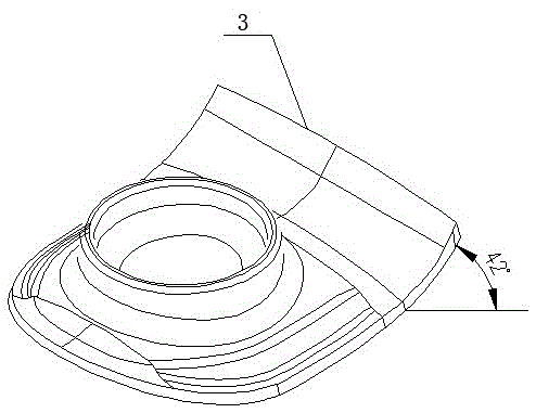
technical field [0001] The invention relates to the field of die forging forming of superalloys, in particular to a die forging forming method of a mounting seat. Background technique [0002] A mount for an aero-engine, the structure of which is shown in figure 1 As shown, its outline size is 227.6×206.8×37.3mm (length×width×height). 5.2mm, and the tail 3 is warped by 42°, which belongs to the thin-walled complex structure. The following problems exist in the die forging process: (1) The shape of the forging is strange, and the blank of the forging is a slab, so the blank is not easy to locate in the forging die during die forging; (2) The tail of the forging has a large degree of warpage, It is easy to generate a strong lateral force during die forging, resulting in a relatively thick tail position and a large displacement of the forging. Contents of the invention [0003] In view of the above problems, the present invention provides a die forging forming method of th...

Claims


Application Information

Patent Timeline
Patent Type & Authority Patents(China)
IPC IPC(8): B21J5/02
Inventor 洪鑫赵顺峰陈瑞钢黄定辉
Owner WUXI TURBINE BLADE
Learn More