Plug skeleton mould

A mold and skeleton technology, which is applied in the field of molds for preparing plug skeletons inside power plugs, can solve problems such as poor contact, unusable plugs, broken and loose metal wire ends, etc.

Inactive Publication Date: 2014-04-02
WUHU SHUNCHENG ELECTRONICS
View PDF5 Cites 5 Cited by
  • Summary
  • Abstract
  • Description
  • Claims
  • Application Information

AI Technical Summary

Problems solved by technology

However, in the process of processing the plug frame made of the existing plug frame into a plug, especially when connecting the wire end to the plug frame, the method of connecting the wire end with the plug frame will cause the metal wire end to be exposed after injection molding, even if the subsequent processing cuts it off , there will s

Method used


Image

  • Plug skeleton mould
  • Plug skeleton mould
  • Plug skeleton mould

Examples


Embodiment Construction

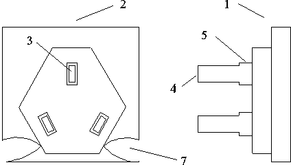
[0014] Such as figure 1 As shown, the mold includes an upper mold 1 and a lower mold 2, and the lower mold 2 has an insertion slot 3, and the insertion slot 3 has a step 4. Before pressing the mould, the upper mold 1 and the lower mold are clamped. close, so that the cutting strip 4 is inserted into the slot 3, and the length H of the cutting strip 4 left (such as figure 1 ) is the thickness of the extruded plug skeleton, generally 2~3mm, the thickness of the plug skeleton in this embodiment is 3mm, because the insert strip 4 has the boss 5, in this embodiment, the thickness of the boss 5 is generally steps 4 are comparable in size to maintain the aesthetic appearance of the plug skeleton.

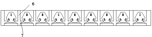
[0015] Such as figure 1 As shown, several mold units are connected to each other, and there is an injection groove 6 for injecting mold material between the mold units, and the mold compound flows through the injection groove 6 and is connected with the lower mold 2 through a concave gro...


PUM


Abstract

The invention discloses a plug skeleton mould, which comprises an upper die and a lower die. The lower die has insert slots, which have steps. The upper die is provided with insert strips corresponding to the insert slots, and the insert strips have bosses. The mould produced by the technical scheme provided by the invention can extrude plug skeletons with beautiful appearance, high qualified rate and long service life. According to a preferred technical scheme of the invention, several mould units are interconnected, injection grooves for injection of mould materials are disposed between the mould units, and the injection grooves are connected to the lower die through sunken grooves, so that a plurality of plug skeletons can be produced by one mould pressing. According to another preferred technical scheme of the invention, the lower die has three insert slots that are distributed in the shape of a Chinese character ''pin''. And the extruded plug skeletons have a beautiful appearance.

Description

technical field [0001] The invention relates to the field of power plugs, in particular to a mold for preparing a plug skeleton inside a power plug. Background technique [0002] In the process of processing and preparing the power plug, it is necessary to connect the metal wire ends exposed after the power cord is peeled to the plug frame, and then inject plastic material so that the rubber material wraps the plug frame to form an insulating plug. However, in the process of processing the plug frame made of the existing plug frame into a plug, especially when connecting the wire end to the plug frame, the method of connecting the wire end with the plug frame will cause the metal wire end to be exposed after injection molding, even if the subsequent processing cuts it off , there will still be hidden dangers of electrical conduction; if the reverse connection method is used, the wire ends will be directly on the plug frame. After injection molding, due to the long-term state...

Claims


Application Information

Patent Timeline
IPC IPC(8): B29C45/26B29C45/14
CPCB29C45/32
Inventor 杨自强田春连曹彩云
Owner WUHU SHUNCHENG ELECTRONICS
Why Eureka
Try Eureka