Method for disc loading of optical thin sheet devices

A technology for optical sheets and devices, applied in grinding devices, grinding machine tools, metal processing equipment, etc., can solve problems affecting processing quality, etc., and achieve the effect of saving raw material costs, overcoming unevenness, and reducing deformation

Inactive Publication Date: 2018-05-25
XUZHOU NORMAL UNIVERSITY
View PDF4 Cites 4 Cited by
  • Summary
  • Abstract
  • Description
  • Claims
  • Application Information

AI Technical Summary

Problems solved by technology

In addition, since the optical thin device is directly placed on the surface of the cast iron sticky disk, the heat is directly transmitted to the optical thin device. During the wax cooling process, due to the thermal stress of the optical thin device itself and the shrinkage force of the wax layer, the optical thin device is deformed, and After the grinding and polishing process is finished, the optical sheet device is lowered. At this time, due to the tension of the wax layer and the release of the stress of the optical sheet device itself, the deformation of the original optical sheet device rebounds, and the polished surface is deformed, which affects the processing quality.

Method used


Image

  • Method for disc loading of optical thin sheet devices
  • Method for disc loading of optical thin sheet devices

Examples


Embodiment 1

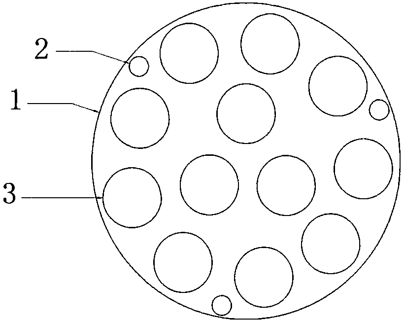
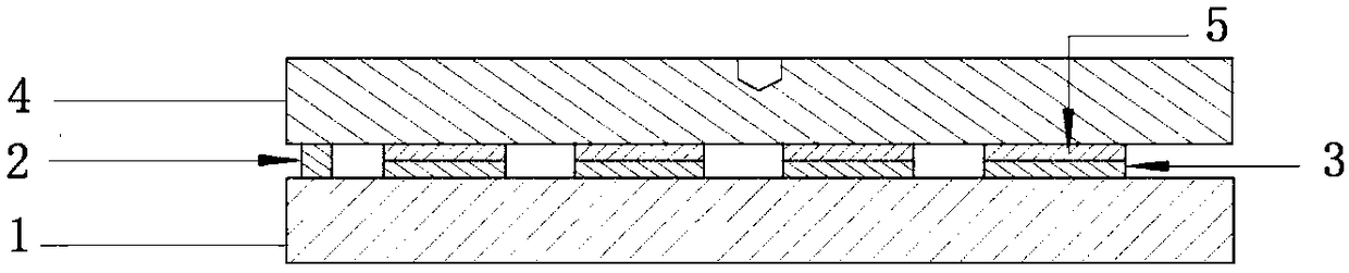
[0029] like figure 1 and figure 2 As shown, in the method for loading an optical thin film device provided in this embodiment, the size of the optical thin film device 3 is 30×1 mm, the quantity is 30, and the melting point of the low-temperature hot melt adhesive is 50 degrees Celsius. Firstly, make the frosted glass flat plate 1 to control its flatness within +0.002mm, and lay two layers of paper on the iron plate of the flat electric heater, so as to prevent the thin optical device 3 from directly contacting the heating plate, resulting in excessive temperature rise and large changes in the internal stress of the device. Spread 30 optical sheet devices 3 on the paper of the electric heater, and turn on the heating power. When the temperature of the optical sheet device 3 is heated to the melting point of the hot melt adhesive, the heating is stopped. Coat one layer of hot-melt adhesive with a thickness of about 1.5 mm on the optical sheet device 3 one by one, and an elec...


PUM


Abstract

The invention provides a method for disc loading of optical thin sheet devices. A ground glass slab with small flatness errors is used as a standard used before disc loading of the optical thin sheetdevices, the upper surfaces of the multiple fixed optical thin sheet devices are located on one plane, the problem that the surfaces of the optical thin sheet devices are uneven is solved, the follow-up grinding time is shortened, and the follow-up grinding difficulty is reduced. In addition, as the upper surfaces of the multiple fixed optical thin sheet devices are on one plane, the workblank thickness, increased by the uneven upper surfaces of the multiple fixed optical thin sheet devices, of the optical thin sheet devices is saved, and raw material cost is saved. Meanwhile, low-melting-point hot melt adhesive is used in the method, the heat stress of the optical thin sheet devices and the contractility of a bonding material are reduced, deformation of the optical thin sheet devices after machining and unloading is reduced, and the machining quality and the product yield are improved.

Description

technical field [0001] The invention relates to the technical field of optical processing, in particular to a method for loading an optical sheet device. Background technique [0002] The existing optical sheet mounting method is to first heat the cast iron sticky plate on an electric furnace, then apply the wax on the surface of the cast iron sticky plate, then place the optical thin film device on the cast iron sticky plate, and wait until the wax is completely immersed in the optical film. Between the sheet device and the cast iron sticky plate, the cast iron sticky plate is removed from the electric furnace, and the optical thin slice device is fixed on the cast iron sticky plate after the wax is cooled and solidified. The disadvantage of this method is that due to the different thickness of the wax layer, the thickness of the optical thin device itself has a tolerance. After the optical thin device is placed on the disk, the upper surfaces of multiple optical thin devic...

Claims


Application Information

Patent Timeline
Patent Type & Authority Applications(China)
IPC IPC(8): B24B37/07B24B37/34
CPCB24B37/07B24B37/34
Inventor 徐斌
Owner XUZHOU NORMAL UNIVERSITY
Why Eureka
Try Eureka