Combination tail lamp for automobile

A technology for automobiles, rear lights

Inactive Publication Date: 2014-04-02
CHONGQING CHANGAN AUTOMOBILE CO LTD
View PDF6 Cites 2 Cited by
  • Summary
  • Abstract
  • Description
  • Claims
  • Application Information

AI Technical Summary

Problems solved by technology

Since the axial directions of the above-mentioned mounting holes and positioning pins are all along the vehicle length direction (that is, the Y direction), the positioning pins cannot effectively restrict the rotation of the combined rear light around the Y-axis during installation, causing the mounting holes to be misplaced, resulting in the combination of rear lights. After installation, the gap between the side wall and the back door is not uniform, resulting in the gap value and the difference between the combined rear light and the side wall and the back door not meeting the design requirements, which affects the appearance of the car

Method used


Image

  • Combination tail lamp for automobile
  • Combination tail lamp for automobile
  • Combination tail lamp for automobile

Examples


Embodiment Construction

[0013] Below in conjunction with accompanying drawing and embodiment the present invention will be further elaborated:

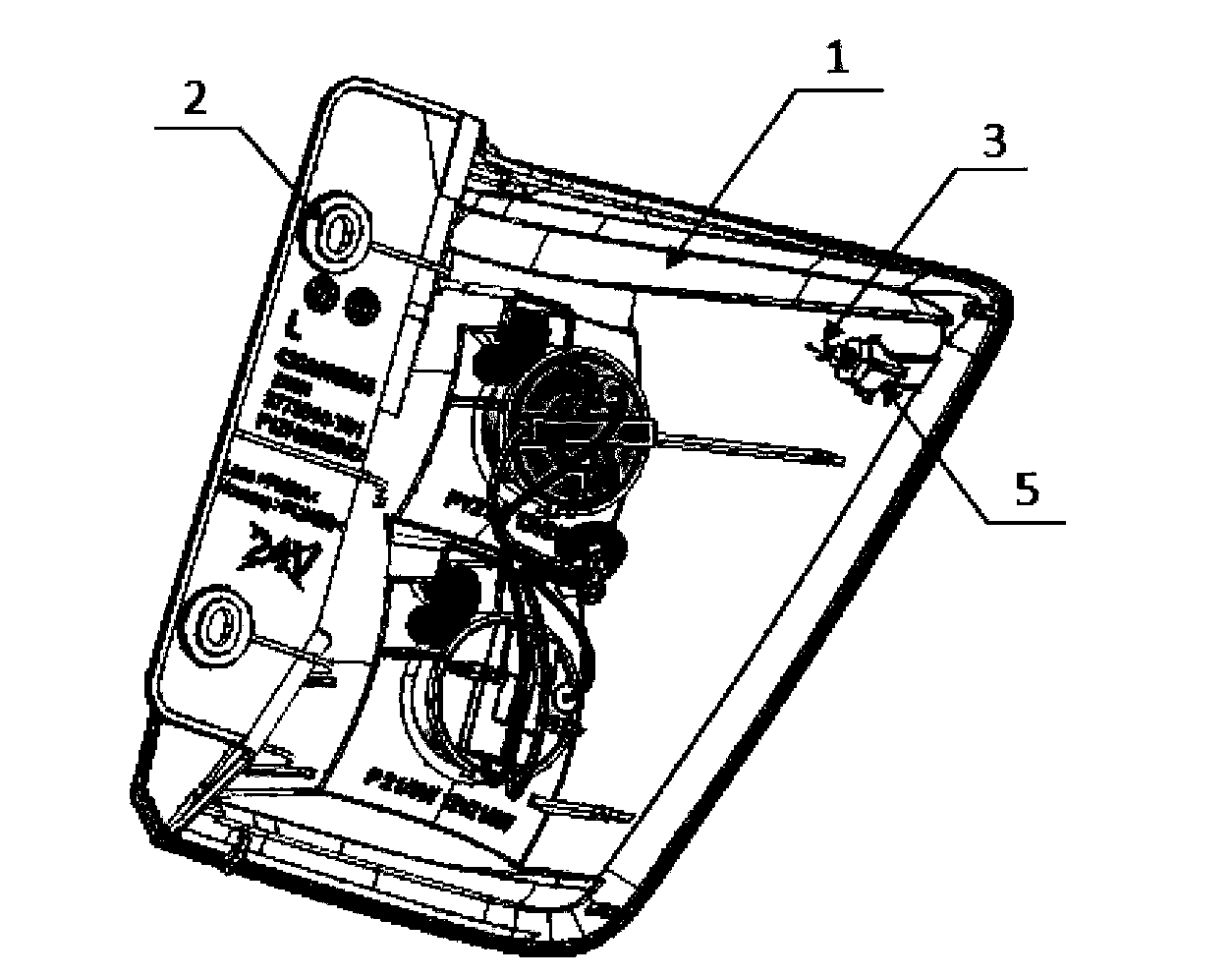
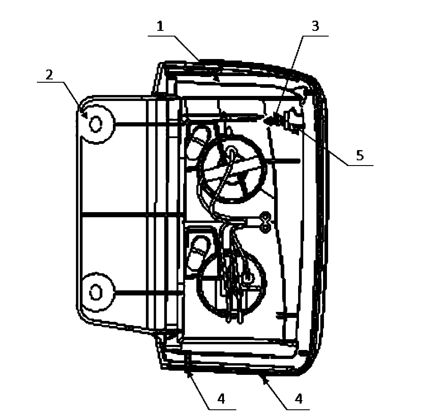
[0014] Such as figure 1 , figure 2 As shown, the automobile combined rear light includes a lamp housing 1, two mounting holes 2 are provided on the rear side of the lamp housing 1, and a cylindrical boss 5 is provided on the inner surface near the sharp corner of the lamp housing 1 side. The boss 5 is 10mm higher than the inner surface of the lamp housing 1, and a positioning pin 3 is arranged on the top of the boss. The positioning pin 3 is made of metal, and it is screwed on the top of the boss 5 by threads. , the axis of the mounting hole 2 is along the Y direction (that is, the vehicle length direction), the axis of the positioning pin 3 is parallel to the horizontal plane and perpendicular to the axis of the mounting hole 2, that is, the positioning pin is along the X direction (vehicle width direction), at the lower edge of the lamp housing 1 Two p...


PUM


Abstract

The invention discloses a combination tail lamp for an automobile. The combination tail lamp comprises a lamp shell; the lamp shell is provided with a mounting hole and a locating pin; the edge of the lamp shell is provided with a locating bulge; the locating pin is positioned on the inner surface close to a sharp corner of a side body of the lamp shell; after the combination tail lamp for the automobile is mounted, the axis of the locating pin is parallel to the horizontal plane and perpendicular to the axis of the mounting hole. The mounting accuracy of the combination tail lamp is improved, and gaps between the combination tail lamp and the side body and between the combination tail lamp and a back door and errors meet design requirements after the combination tail lamp is mounted.

Description

technical field [0001] The invention relates to an automobile component, in particular to an automobile combined rear light. Background technique [0002] At present, the combined rear lights of cars used in miniature cars are mainly composed of light distribution mirrors, lamp housings, bulbs, and wiring harnesses. Such as Figure 5 Shown is the existing combined rear light of an automobile. Two mounting holes 2 and a positioning pin 3 are arranged on the lamp housing. In the middle of the two lamp chambers in the housing, there are multiple positioning protrusions on the edge of the lamp housing. When the combined rear light is installed on the vehicle body, the positioning pins are used for positioning. The positioning protrusions cooperate with the body sheet metal parts, and then screws are used to Fix the combined rear light on the vehicle body through the above mounting holes. Since the axial directions of the above-mentioned mounting holes and positioning pins are ...

Claims


Application Information

Patent Timeline
Patent Type & Authority Applications(China)
IPC IPC(8): B60Q1/30
Inventor 王姝刘江涛周兵舰
Owner CHONGQING CHANGAN AUTOMOBILE CO LTD
Why Eureka
Try Eureka