Hydraulic system with priority function

A technology of hydraulic system and function, applied in the field of hydraulic system with priority function, to achieve the effect of improving performance and low cost

Active Publication Date: 2014-04-02
LIUZHOU LIUGONG EXCAVATORS +2
View PDF5 Cites 3 Cited by
  • Summary
  • Abstract
  • Description
  • Claims
  • Application Information

AI Technical Summary

Problems solved by technology

[0005] The purpose of the present invention is to provide a hydraulic system with priority functions that can solve the problem of compound action flow distribution

Method used


Image

  • Hydraulic system with priority function
  • Hydraulic system with priority function
  • Hydraulic system with priority function

Examples


Embodiment Construction

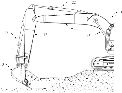
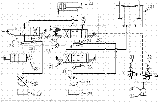
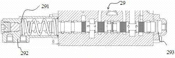
[0016] Such as figure 1 , 2 As shown, the present invention is applied to the machine 1 as a hydraulic excavator, including a first main pump 24, a second main pump 25, a first hydraulic actuator 21, a second hydraulic actuator 22, a first hand pilot hydraulic valve 31, The second hand pilot hydraulic valve 32 and the pilot hydraulic pump 30, the first main pump 24 supplies oil to the second hydraulic actuator 22 or to the first hydraulic actuator 21 through the first main pump switching valve group or to the second hydraulic actuator 21 at the same time. The first hydraulic actuator 21 and the second hydraulic actuator oil supply 22 are switched, and the second main pump 25 supplies oil to the first hydraulic actuator 21 and the second hydraulic actuator 22 through the second main pump switching valve group. switching, the first main pump switching valve group includes a first reversing valve 26 and a third reversing valve 28, the first reversing valve 26 is used to switch b...


PUM


Abstract

The invention relates to a hydraulic system with a priority function. According to the hydraulic system, a first main pump carries out the switchover of supplying oil to a second or first hydraulic actuator or simultaneously supplying oil to the first and second hydraulic actuators through a first main pump switching valve set, a second main pump carries out the switchover of supplying oil to the first hydraulic actuator or the second hydraulic actuator through a second main pump switching valve set, a fourth reversing valve is provided with a valve core displacement limit device, and the valve core displacement limit device comprises a valve core which is located in the movement direction of a valve core of the fourth reversing valve and a control oil port which is communicated with a first manual pilot hydraulic valve. The hydraulic system has the advantages that the problem of flow distribution in compound action can be solved, a machine of the system has the priority function, the performance of the collaborative action of two or more actuators can be improved, and the required elements are fewer, simple and reliable and are low in cost; by applying the system, an operator can complete expected operation in an easier manner, and meanwhile, the performance of separate operations or other complex operations cannot be affected.

Description

technical field [0001] The present invention relates to a hydraulic system used in construction machines, in particular to a hydraulic system with priority functions for construction machines such as walking machines. Background technique [0002] General walking machinery, such as hydraulic excavators, the hydraulic system is a dual main pump system, and the hydraulic circuit of the boom and stick is the confluence of the double pumps. [0003] There will be such a problem. When digging and leveling the land, the machine needs to use the boom and stick, and even the bucket at the same time. The load of the hydraulic circuit of the stick is larger than that of the hydraulic circuit of the boom, and the flow of the hydraulic system tends to flow The boom hydraulic circuit with low load, the stick hydraulic circuit cannot get enough flow, resulting in slow and weak digging of the stick. [0004] In order to solve the above problems, there are currently some applications ...

Claims


Application Information

Patent Timeline
Patent Type & Authority Applications(China)
IPC IPC(8): F15B11/02F15B13/02
Inventor 李文新唐涛李欲江刘剑
Owner LIUZHOU LIUGONG EXCAVATORS
Why Eureka
Try Eureka