Device capable of indicating packing compression status of valve stem

A technology of packing compaction and indicating valve, applied in valve device, valve details, engine components, etc., can solve problems such as affecting the use effect of packing, unable to accurately achieve the proper compacting state of packing, etc., to achieve convenient daily maintenance, simple structure, The effect of prolonging the service life

Active Publication Date: 2014-04-02
NO 11 INST OF NO 6 ACADEMY OF CHINA AEROSPACE SCI & TECH
View PDF7 Cites 2 Cited by
  • Summary
  • Abstract
  • Description
  • Claims
  • Application Information

AI Technical Summary

Problems solved by technology

[0003] In order to solve the existing technical problems of lack of packing compaction state indicator device, unable to accurately reach the proper compaction state of the packing, and affecting the use effect of the packing, the present invention provides a device with an indication of the packing compaction state of the valve stem, which can Provides clear information on the proper packing state, preventing packing over or under pressure, extending packing life and maintenance intervals

Method used


Image

  • Device capable of indicating packing compression status of valve stem
  • Device capable of indicating packing compression status of valve stem
  • Device capable of indicating packing compression status of valve stem

Examples


Embodiment 1

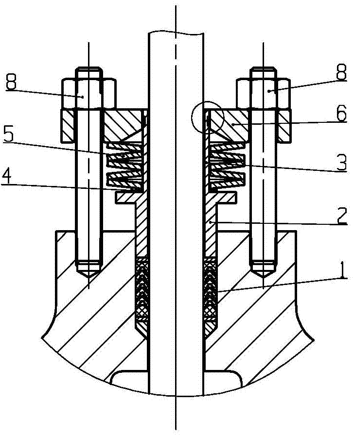
[0058] Example 1 as figure 1 , 2 As shown, the packing seal structure is compressed by the fastener 8 by pressing the packing gland 6 to compress the disc spring 5, the deformation force of the disc spring 5 acts on the packing cylinder 2, and compresses the packing 1, wherein the packing pressure The cylinder 2 and the guide cylinder 3 are fixedly connected.

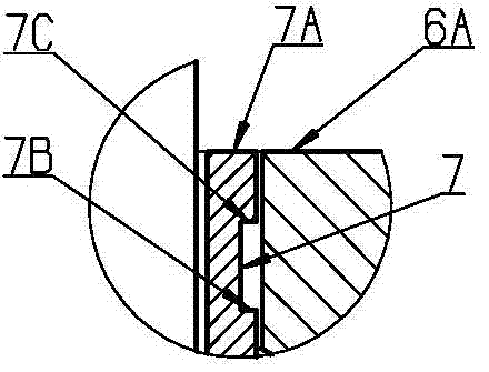
[0059] The specific implementation of the packing compaction state indicating structure of the packing sealing structure is as follows: an annular groove 7 is formed on the guide cylinder 3 by machining, and eye-catching pigments are filled in the annular groove 7 . The lower end surface of the annular groove 7 is the maximum compression scale indication surface 7B, the upper end surface of the annular groove is the minimum compression scale indication surface 7C, the upper end surface of the guide cylinder 3 is the zero scale indication surface 7A, and the upper surface of the packing gland 6 is It is pointer 6A. Befo...

Embodiment 2

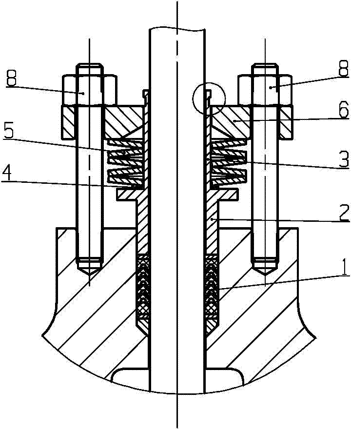
[0063] Such as Figure 6 , 7 As shown, the packing sealing structure adopts a small disc spring 5, which is installed on the fastener 8, and the disc spring 5 is directly compressed by the fastener 8, and the resultant force of deformation of several groups of disc springs 5 ​​acts on the packing gland 6 , and compress the packing 1 through the packing cylinder 2.

[0064] The specific implementation of the packing compaction state indicating structure of the packing sealing structure is as follows: each set of pressing devices composed of fasteners 8 and disc springs 5 ​​is provided with the same compacting state indicating structure. An annular groove 7 is formed on the guide cylinder 3 by machining, and eye-catching paint is filled in the annular groove 7 . The upper end surface of the annular groove 7 is the maximum compression scale indication surface 7B, the lower end surface of the annular groove is the minimum compression scale indication surface 7C, the lower end su...


PUM


Abstract

The invention relates to a device capable of indicating the packing compression status of a valve stem. The device comprises a fastening part, a compressioncover, an elastic assembly, a packing compression cylinder and a guide cylinder, wherein one end of the packing compression cylinder acts onto the compression packing in a packing box, the guide cylinder is fixed to the other end of the packing compression cylinder, the elastic assembly is sleeved onto the guide cylinder, one end of the elastic assembly contacts with the packing compression cylinder, the other end of the elastic assembly contacts with the lower end surface of the compression cover, and the fastening part is fixed on the compression cover and acts onto the compression packing in the packing box through the compression cover, the elastic assembly and the packing compression cylinder. The device further comprises an indication assembly which comprises an annular groove arranged on the guide cylinder and a pointer arranged on the upper end surface of the compression cover. The device solves the technical problem that the existing device does not have the indication assembly and cannot indicate the packing compression status, and can provide clear information whether the packing compression status is appropriate in order to prevent overpressure or pressure shortage of the packing and prolong service life and maintenance period of the packing.

Description

technical field [0001] The invention relates to valve stem seals for valves, especially with a device for indicating the tightness of valve stem packing. Background technique [0002] Packing stem seal is the most widely used stem seal structure at present. In order to control the compression force of the packing, the structure of "filler + disc spring" is usually adopted, that is, the compression disc spring is used to provide the required compression force for the packing seal. , which can not only ensure a relatively constant pressing force, but also automatically compensate for the reduction of sealing stress caused by creep and wear. For the existing valve stem packing seal structure, since there is no indication structure for the packing compaction state, the packing compaction force is mainly determined by the experience of the operator during assembly and use, and human factors are greatly affected, which is prone to shortening due to underpressure of the packing. T...

Claims


Application Information

Patent Timeline
Patent Type & Authority Applications(China)
IPC IPC(8): F16K41/02F16K37/00
CPCF16K37/0016F16K41/02
Inventor 李小明王波许长华袁军杨振宁王伟
Owner NO 11 INST OF NO 6 ACADEMY OF CHINA AEROSPACE SCI & TECH
Why Eureka
Try Eureka