
Filling connector, container, filling method and filling nozzle

A technology for connectors and containers, applied in container filling methods, equipment loaded into pressure vessels, lifting valves, etc., to achieve a high degree of safety

Active Publication Date: 2014-04-02
LAIR LIQUIDE SA POUR LETUDE & LEXPLOITATION DES PROCEDES GEORGES CLAUDE
View PDF8 Cites 10 Cited by
  • Summary
  • Abstract
  • Description
  • Claims
  • Application Information

AI Technical Summary

Problems solved by technology

This requires frequent replacement of O-rings

Method used


Image

  • Filling connector, container, filling method and filling nozzle
  • Filling connector, container, filling method and filling nozzle
  • Filling connector, container, filling method and filling nozzle

Examples


Embodiment Construction

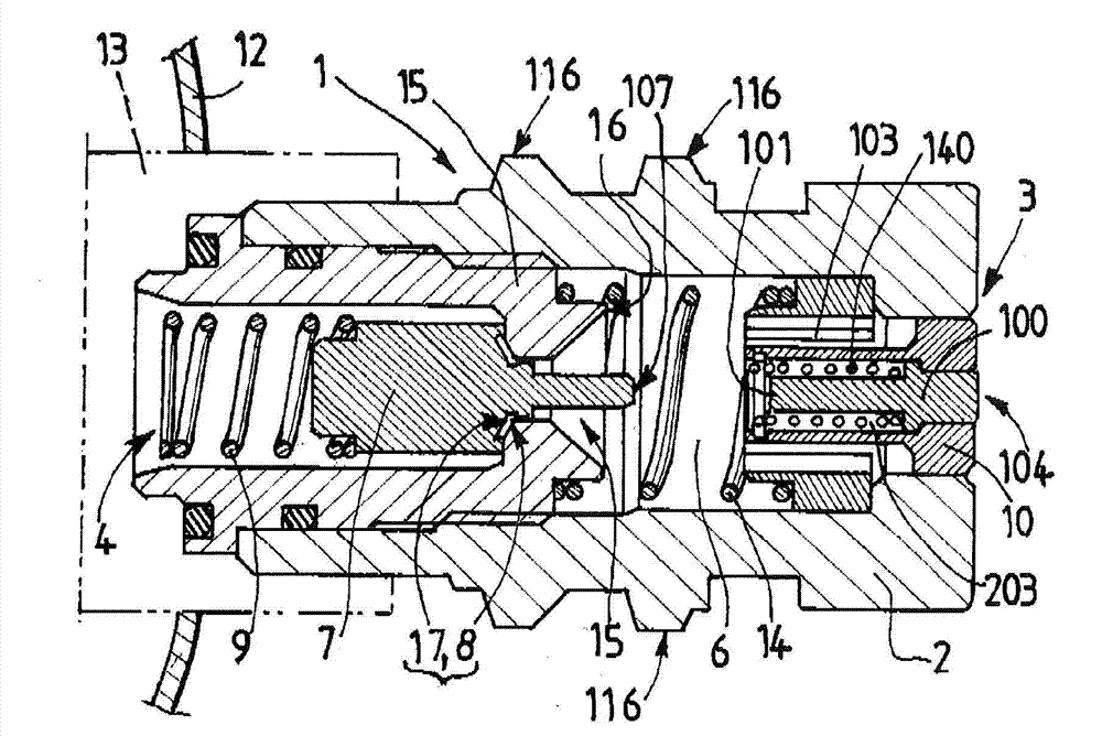
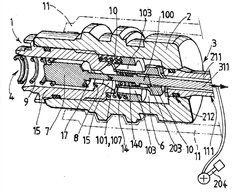
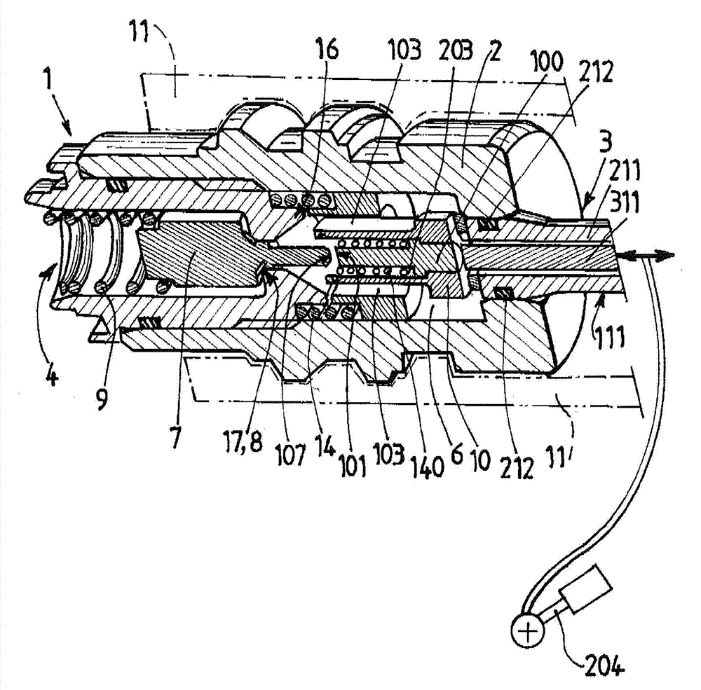
[0107] see figure 1 , the stuffing connector 1 comprises a body 2 which is, for example, substantially cylindrical. The body 2 delimits an internal filling circuit 6 between an upstream end 3 for connection to a filling socket and a downstream end 4 for connection to a container of pressurized gas (via, for example, the interior of a tap. circuit).

[0108] exist figure 1 In the example of , the downstream end of the portion of the connector 1 is fixed to the faucet 13 , for example by screwing. The tap 13 (shown in dashed lines) is secured to the orifice of a container of pressurized fluid, such as a bottle 12 .

[0109] The upstream end 3 of the circuit 6 (and of the connector 1 ) can be closed again selectively by a dust valve element 10 , 100 movable in the body 2 of the connector.

[0110] The anti-dust valve element 10, 100 is selectively movable (preferably translated) in the body 2 between an upstream position in which the upstream end 3 of the circuit 6 is closed ...


PUM


Abstract

The invention relates to a filling connector which includes a body (2) defining an inner filling circuit (6) between an upstream end (3) and a downstream end (4), the connector including a valve (7) for mobile isolation relative to a seat (8) between an upstream position for closing the circuit and a downstream position for opening the circuit, the connector (1) also including a dust valve (10, 100) positioned upstream from the isolation valve (7), characterised in that the dust valve can be moved selectively downstream, either to a first predetermined downstream position, referred to as a 'contactless' position, opening the upstream end of the circuit, and in which the downstream end of the dust valve does not push the upstream end of the isolation valve, or to a second predetermined downstream position, referred to as 'contact' position, opening the upstream end of the circuit, and in which the downstream end of the dust valve pushes an upstream end of the mobile isolation valve, the dust valve comprising one or more passages (103) for guiding at least one portion of the stream of fluid passing through the body of the dust valve (10) from the upstream end (3) to the downstream end; the dust valve including first (10) and second (100) concentric parts capable of being moved relative to one another in the upstream-downstream direction.

Description

technical field [0001] The present invention relates to a filling connector, a tap (valve, switch (of fluid, etc.)), a container for pressurized fluid, a filling method and a filling prise using such a connector. [0002] The invention relates more particularly to a filling connector for a container of pressurized fluid, for cooperating with a filling socket to allow filling of said container with this connector, which connector is included upstream for connection to the filling socket A body portion defining an internal filling circuit between the end and a downstream end for connecting to a container, the connector includes a body that can be positioned relative to the seat between an upstream position where the circuit is in a closed state and a downstream position where the circuit is in an open state a moving isolation valve element that is urged toward its upstream position by a reset member, the connector also includes a dust valve element disposed upstream of the isola...

Claims


Application Information

Patent Timeline
IPC IPC(8): F16K1/30
CPCF16K1/308F16K1/303F17C5/06
Inventor A·弗雷纳尔C·曼斯考特P·皮索
Owner LAIR LIQUIDE SA POUR LETUDE & LEXPLOITATION DES PROCEDES GEORGES CLAUDE
Learn More