
A static pressure system damping copper tube manufacturing device

A technology for manufacturing devices and copper tubes, which is applied in the field of manufacturing devices for damping copper tubes in static pressure systems, can solve problems such as poor manufacturing accuracy, and achieve the effects of consistent pitch, uniform and smooth copper tubes, and beautiful precision

Active Publication Date: 2015-12-02
TIANSHUI SPARK MACHINE TOOL
View PDF8 Cites 0 Cited by
  • Summary
  • Abstract
  • Description
  • Claims
  • Application Information

AI Technical Summary

Problems solved by technology

[0003] The purpose of the present invention is to avoid the defects of poor manufacturing precision in the prior art and provide a device for manufacturing damping copper tubes for static pressure systems, which uses gear shafts to control the diameter of the damping tube windings, and uses screw rods to control the pitch of the damping tube windings, thereby effectively solving the current problem. There are flaws in the technology

Method used


Image

  • A static pressure system damping copper tube manufacturing device
  • A static pressure system damping copper tube manufacturing device
  • A static pressure system damping copper tube manufacturing device

Examples


Embodiment Construction

[0017] The principles and features of the present invention are described below in conjunction with the accompanying drawings, and the examples given are only used to explain the present invention, and are not intended to limit the scope of the present invention.

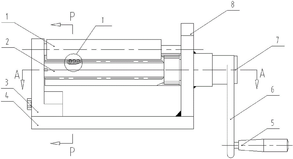
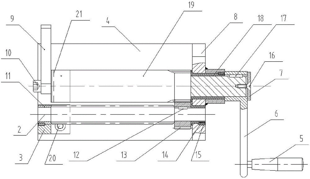
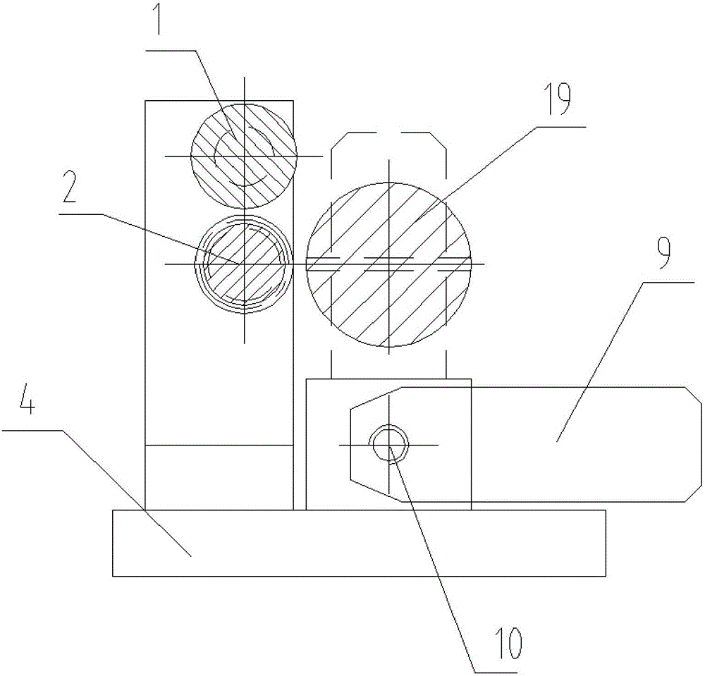
[0018] Such as Figures 1 to 4 As shown, the device for manufacturing a damping copper tube for a static pressure system is characterized in that it includes a bottom plate 4, a left bracket 3 and a right bracket 8 are respectively arranged on the bottom plate 4, and the gear shaft 19 and the screw mandrel 2 are correspondingly installed on the left bracket 3 and the right bracket 8, the gear 13 at one end of the screw mandrel 2 meshes with the end of the gear shaft 19, the end of the gear shaft 19 is also provided with a groove 21, and the end of the gear shaft 19 stretching out from the right bracket 8 is provided with a handle 6. The handle 6 is provided with a handle 5, the left bracket 3 is also provided with a...


PUM


Abstract

The invention relates to the technical field of damping copper tube winding equipment of a static pressure system of a machine tool, and specifically relates to a preparation device for a damping copper tube of a static pressure system. The preparation device is characterized by comprising a baseplate, wherein a left support and a right support are respectively arranged on the baseplate, a gear shaft and a lead screw are correspondingly arranged on the left support and the right support, a gear at one end of the lead screw is engaged with the end of the gear shaft which is further provided with a slot; the end of the gear shaft which protrudes the right support is provided with a handgrip, a handle is arranged on the handgrip, the left support is further provided with a baffle corresponding to the end of the gear shaft, and the left support and the right support at the upper part of the lead screw are correspondingly provided with compression shafts. A thread pitch which unwinds a copper tube is controlled by the lead screw, and the diameter of a damping pipe winding is controlled by the gear shaft; the gear shaft is driven to rotate by the handle, the gear and the lead screw are driven to rotate by the gear shaft, and the copper tube is pushed to move forwards when the lead screw is being rotated. The thread pitches of the damping copper tubes prepared by the device are consistent, and the copper tube is uniform and smooth in surface, attractive in appearance and high in precision.

Description

technical field [0001] The invention relates to the technical field of coiling equipment for damping copper tubes in static pressure systems of machine tools, in particular to a manufacturing device for damping copper tubes in static pressure systems. Background technique [0002] In the prior art, when the static pressure system is installed on the machine tool, the copper tube needs to be wound on a shaft or a pipe with a certain diameter when winding the damping copper tube. Since the copper tube is relatively thin and its diameter is about 4mm, and the copper tube is relatively soft, it is difficult to straighten it once it is bent. Manual operation is usually used, and the proficiency of workers is different. The pitch of the damping copper tube wound out by this method is inconsistent, and many parts of the copper tube are flattened, resulting in unsightly appearance and low precision. Especially when the constant static pressure system of the machine tool adjusts the...

Claims


Application Information

Patent Timeline
Patent Type & Authority Patents(China)
IPC IPC(8): B21D11/06
Inventor 李维谦陈森
Owner TIANSHUI SPARK MACHINE TOOL
Learn More