
Model core conveying trolley

A technology for conveying trolleys and conveying tables, which is applied to tires, other household appliances, household appliances, etc., can solve problems such as freedom degree restriction, track forming curved parts, discontinuous parts, and complicated operations.

Active Publication Date: 2014-04-09
SUMITOMO RUBBER IND LTD
View PDF2 Cites 0 Cited by
  • Summary
  • Abstract
  • Description
  • Claims
  • Application Information

AI Technical Summary

Problems solved by technology

[0005] However, in the above-mentioned production line, when moving the core transport trolley from the beginning to the end of the production line, the moving distance of the core transport trolley becomes very long.
Therefore, there is a problem that the operation of power supply to the core transport trolley becomes complicated
Moreover, it is necessary to form the above-mentioned rail as a whole in a straight line and / or in a circular arc shape with a sufficiently large radius, and it is also impossible to form curved parts, discontinuous parts, etc. in the rail.
Therefore, the degree of freedom of the track, and thus the degree of freedom of the factory design, is greatly restricted, and it also hinders the miniaturization of the factory.

Method used


Image

  • Model core conveying trolley
  • Model core conveying trolley
  • Model core conveying trolley

Examples


Embodiment Construction

[0041] Hereinafter, embodiments of the present invention will be described in detail.

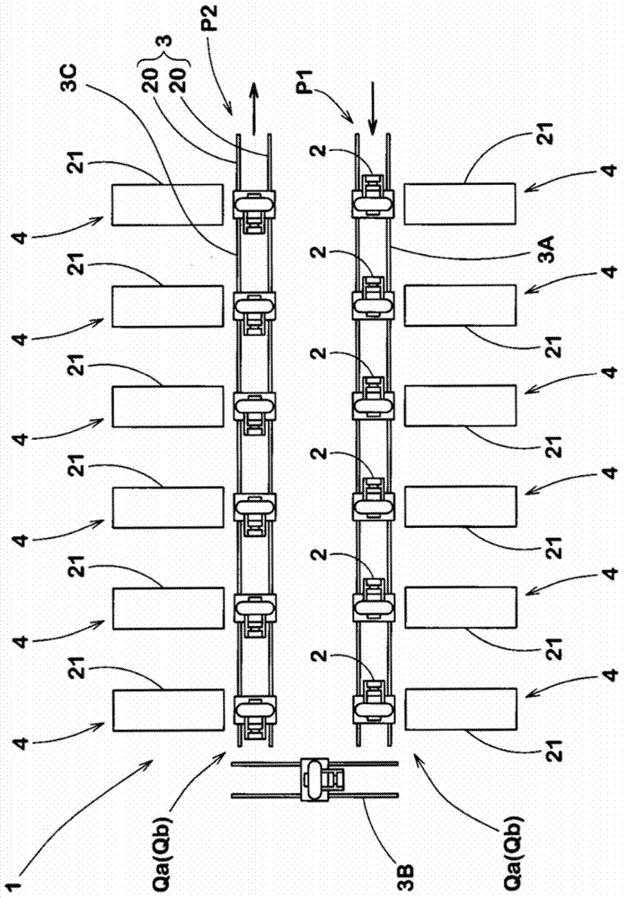
[0042] figure 1An embodiment of a green tire production line 1 using the core conveying trolley 2 of the present invention is schematically shown in . The raw tire production line 1 has a rail 3 on which a core transport trolley 2 runs; and a plurality of work stations 4 arranged along the rail 3 . Then, each work station 4 sticks the tire components T on the outer surface of the rigid core 5 moving on the rail 3 according to the order of the arrangement described above, thereby forming the green tire 6 .

[0043] Figure 8 An example of a green tire 6 formed on the manufacturing line 1 described above is shown in FIG. In this example, the green tire 6 is formed to include:

[0044] (a) a carcass T1 extending from the tread portion 6a to the bead portion 6c via the sidewall portion 6b;

[0045] (b) a belt layer T2 arranged radially outside the carcass T1 and inside the tread portion 6 ...


PUM


Abstract

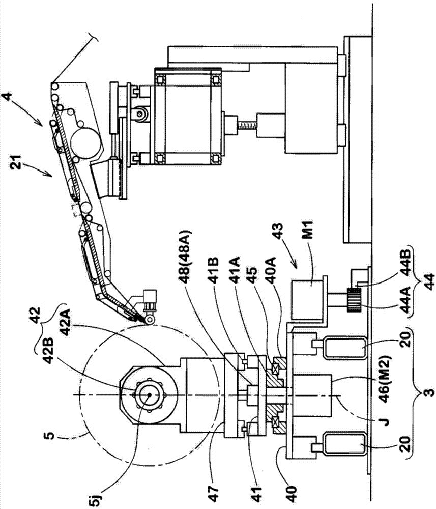
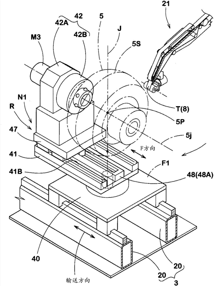
The invention provides a model core conveying trolley. Handing over of model cores between two model core conveying trolleys on a track is allowed. The model core conveying trolley comprises a conveying bench capable of moving along the track, a rotary bench supported on the conveying bench and revolving about a vertical revolving axis, a horizontal moving bench which is supported on the rotary bench, and can be horizontally moved to a second position from a first position along a horizontal F directional line passing through a revolving axis, and a model core supporting bench which is supported on the horizontal moving bench and can be connected with a supporting shaft connection portion at one side of a rigid model core in a dismounting free means. When the F directional line is in parallel to the conveying direction under a revolving referential state, and on the second position, the equatorial plane of the rigid model core is on a position outside than the conveying bench and the horizontal moving bench relative the conveying direction.

Description

technical field [0001] The present invention relates to a core transfer cart capable of holding a rigid core and transferring the rigid core between two core transfer carts on a rail. Background technique [0002] In recent years, a method of forming a tire using a rigid core (hereinafter referred to as “core processing method”) has been proposed in order to improve the forming accuracy of the tire (for example, refer to Patent Documents 1 and 2). The above-mentioned rigid core has approximately the same outer shape as the tire inner surface of the vulcanized tire, and the inner liner, carcass ply, belt ply, sidewall rubber, and tire are sequentially pasted on the outer surface of the rigid core. Rubber and other tire components are used to form raw tires. In addition, the above-mentioned green tire is put into a vulcanization mold together with a rigid core, thereby sandwiching the above-mentioned green tire between the rigid core as an inner mold and the vulcanization mol...

Claims


Application Information

Patent Timeline
IPC IPC(8): B29D30/10
Inventor 鬼松博幸
Owner SUMITOMO RUBBER IND LTD
Learn More