Accelerator equipment for vehicles
A technology of accelerators and vehicles, which is applied to mechanical equipment, vehicle parts, instruments, etc., and can solve problems such as enlargement
- Summary
- Abstract
- Description
- Claims
- Application Information
AI Technical Summary
Problems solved by technology
Method used
Image

Examples
no. 1 example )
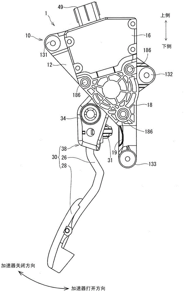
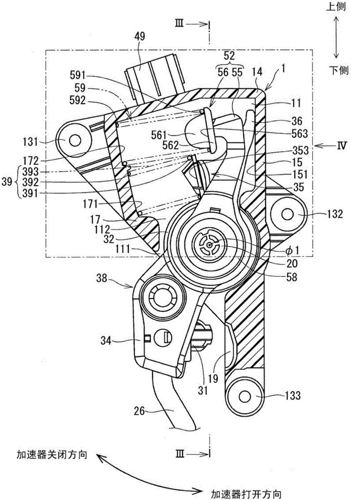
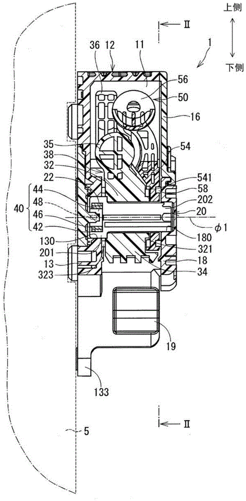
[0014] figure 1 4 shows an accelerator device according to a first embodiment of the present invention. The accelerator device 1 is an input device that is manipulated by a driver of a vehicle (for example, an automobile) to determine a valve opening degree of a throttle valve of the vehicle's internal combustion engine. The accelerator device 1 is an electronic device that transmits an electric signal indicating the amount of depression of the accelerator pedal 28 by the driver's foot of the vehicle to the electronic control device. The electronic control unit drives the throttle valve through an accelerator transmission mechanism (not shown) based on the depression amount of the pedal 28 and other information.
[0015] The accelerator apparatus 1 includes a support member 10 , a shaft 20 , a manipulation member 30 , a return spring 39 , a rotation angle sensor (serving as rotation angle sensing means) 40 , and a hysteresis mechanism 50 . In the following description, Fig...
no. 2 example )
[0061] Next, refer to Figure 5 An accelerator device according to a second embodiment of the present invention is described. In the second embodiment, the shape of the return spring at the time of full accelerator closing is different from that in the first embodiment. In the following description, components similar to those of the first embodiment will be designated by the same reference numerals, and will not be further described for simplicity.
[0062] Figure 5 A cross-sectional area of the accelerator device of the second embodiment is shown.
[0063] The spring receiving portion 65 protrudes toward the front section 17 at the full closing side stopper portion 36 extending from the return raised portion 32 . The spring receiving portion 65 forms a return spring engagement surface 653 with which one end portion 691 of the return spring 69 is engaged.
[0064] While one end portion 691 of the return spring 69 is engaged with the return spring engaging surface 653 o...
PUM
 Abstract
Description
Claims
Application Information
 - R&D
- Intellectual Property
- Life Sciences
- Materials
- Tech Scout
- Unparalleled Data Quality
- Higher Quality Content
- 60% Fewer Hallucinations
Browse by: Latest US Patents, China's latest patents, Technical Efficacy Thesaurus, Application Domain, Technology Topic, Popular Technical Reports.
© 2025 PatSnap. All rights reserved.Legal|Privacy policy|Modern Slavery Act Transparency Statement|Sitemap|About US| Contact US: help@patsnap.com