Tube stretching device and tube folding machine
A technology of tubular objects and edge folding machines, which is applied in the direction of mechanical cleaning, fabric surface trimming, shaping/elongation of circular fabrics, etc., which can solve the problems of high labor intensity for workers or processors, different product quality, and inaccurate dimensions, etc. problems, to achieve the effect of simple structure, high quality and high production efficiency
- Summary
- Abstract
- Description
- Claims
- Application Information
AI Technical Summary
Problems solved by technology
Method used
Image
Examples
Embodiment 1
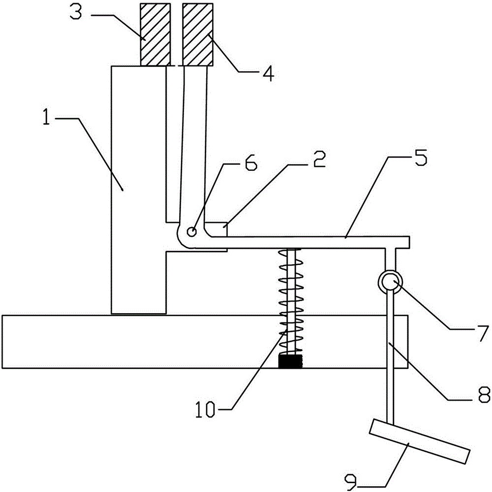
[0045] Such as figure 1 As shown, the stretching device for tubular objects in this embodiment includes a vertically arranged first support plate 1; the first support plate extends horizontally outward to form a second support plate 2;
[0046] The top of the first support plate 1 is provided with a fixed wide arm 3; the extension end of the second support plate 2 is movably connected with a bent plate 5 through a shaft pin 6; the bent plate is composed of two straight plates at a certain angle; The pivot pin is located at the junction of the two straight plates of the bent plate 5; the top end of the bent plate 5 is provided with a movable wide arm 4, and the bottom end conflicts with a vertically arranged elastic structure 10;
[0047] When the bottom end of the curved plate 5 is not subjected to downward external force, the amount of compression of the elastic structure 10 is the smallest, and the movable wide arm 4 and the fixed wide arm 3 are at the same horizontal height...
Embodiment 2
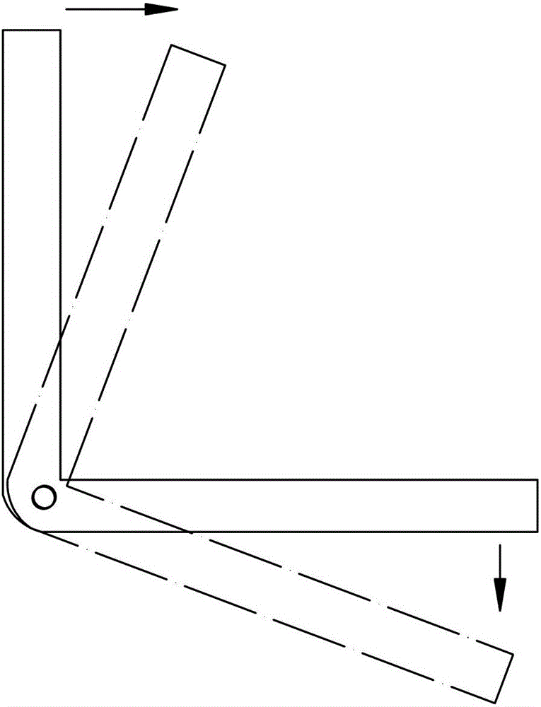
[0056] On the basis of the first embodiment, the device for stretching tubular objects in this embodiment is further composed of a first straight plate and a second straight plate connected to each other to form a right angle. That is, the angle formed by the two straight plates is 90°.
[0057] Further, a suspension ring 7 is connected to the end of the second straight board away from the first straight board; the suspension ring 7 is connected to a pedal 9 through a rope 8 .
[0058] During operation, the pedal 9 moves up and down by an external force, thereby pulling the rope 8 and the suspension ring 7 to move up and down, thereby pulling the second straight board to move downward. When the second straight board moves downward, the elastic structure 10 is compressed, and the first straight board moves downward. The shaft pin 6 rotates to the right as the rotation point, and during the rotation, the movable stretching arm 4 moves to the right away from the fixed stretching ...
no. 1 example
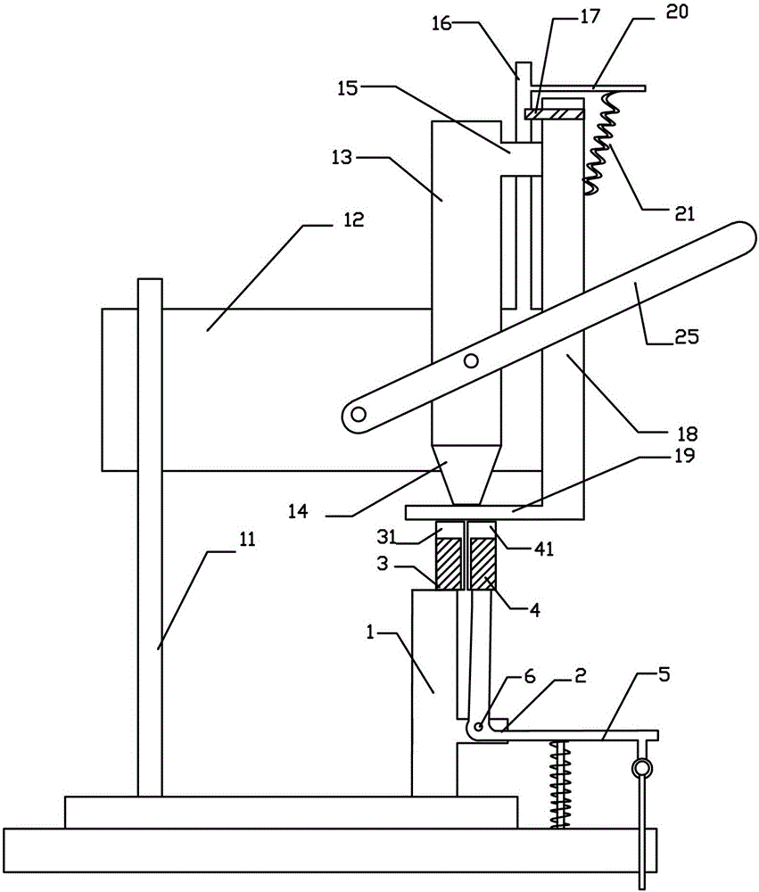
[0062] Such as image 3 As shown, the tubular object folding machine in this embodiment includes any one of the tubular object stretching devices described in Embodiment 1 to Embodiment 2, a stretching tube, and a movable press arranged at the upper end of the tubular object stretching device. edge device;
[0063] The stretched wide tube is composed of two semicircular first stretched wide tube walls 31 and a second stretched wide tube wall 41; the first stretched wide wall 31 is located on the outside of the fixed stretched wide arm 3; The second widening tube wall 41 is located on the outside of the movable widening arm 4;
[0064] The upper edge of the first widened tube wall 31 is higher than the top of the fixed widened arm 3; the upper edge of the second widened tube wall 41 is higher than the top of the movable widened arm 4;
[0065] Wherein, the movable edge-holding device moves downward to press the part of the tubular object that is sleeved on the outside of the ...
PUM
 Abstract
Description
Claims
Application Information
 - R&D
- Intellectual Property
- Life Sciences
- Materials
- Tech Scout
- Unparalleled Data Quality
- Higher Quality Content
- 60% Fewer Hallucinations
Browse by: Latest US Patents, China's latest patents, Technical Efficacy Thesaurus, Application Domain, Technology Topic, Popular Technical Reports.
© 2025 PatSnap. All rights reserved.Legal|Privacy policy|Modern Slavery Act Transparency Statement|Sitemap|About US| Contact US: help@patsnap.com


