Oil well broken rod blowout preventer

A blowout preventer and broken rod technology, which is used in wellbore/well components, earthwork drilling, sealing/packaging, etc. Improves life and prevents wear and tear

Active Publication Date: 2016-05-04
段鹏飞 +1
View PDF9 Cites 0 Cited by
  • Summary
  • Abstract
  • Description
  • Claims
  • Application Information

AI Technical Summary

Problems solved by technology

[0003] The purpose of the present invention is to provide an oil well broken rod blowout preventer, which can effectively solve the problem that the existing oil pumping well broken rod blowout preventer has damaged polished rods or the sealing steel ball cannot achieve the sealing effect due to wear

Method used


Image

  • Oil well broken rod blowout preventer
  • Oil well broken rod blowout preventer
  • Oil well broken rod blowout preventer

Examples


Embodiment 1

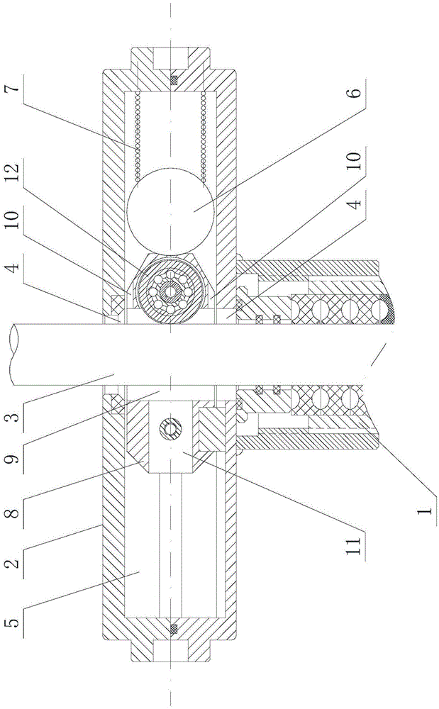
[0022] refer to figure 1 It is the first embodiment of the oil well broken rod blowout prevention device of the present invention. The oil well broken rod blowout preventer includes a casing 2 docked with the packing box 1, and the casing 2 is provided with a through hole 4 for the light rod 3 to pass through. , the housing 2 is provided with a plugging cavity 5 communicating with the through hole 4, and the plugging cavity 5 is provided with a steel ball 6 for plugging the through hole 4, and the plugging cavity 5 behind the steel ball 6 is A first elastic member 7 that ejects the steel ball 6 is provided inside, and a control device that prevents the steel ball 6 from contacting the polished rod 3 when the polished rod 3 is in normal operation is provided inside the housing 2

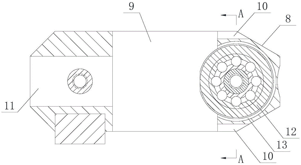
[0023] Such as figure 2 As shown, the control device includes an anti-wear block 8 arranged between the polished rod 3 and the steel ball 6, the anti-wear block 8 is provided with a middle hole 9 fo...

Embodiment 2

[0026] refer to Figure 4 The difference from Embodiment 1 is that the structure of the control device is different. The lower part of the through hole 4 is provided with a sealing ring 19 to prevent oil leakage. The push rod 21 of the boss 20, the push rod 21 is arranged between the steel ball 6 and the first elastic member 7, a step 22 is provided in the sealing cavity 5, the push rod 21, the boss 20, the step 22 and the side wall of the sealing chamber 5 enclose a closed pressure chamber 23, and the housing 2 is provided with a pressure channel 24 that communicates the pressure chamber 23 with the through hole 4 below the sealing ring 19, and the first elastic member 7 compresses The thrust produced on the push rod 21 is equal to the thrust generated by the oil entering the pressure chamber 23 on the boss 20. When the first elastic member 7 is compressed, the distance between the front end of the push rod 21 and the polished rod 3 is greater than the diameter of the steel b...

Embodiment 3

[0030] Such as Figure 5 As shown, the control device includes a control cavity 25 arranged in the housing 2 and communicated with the through hole 4, a pin 26 pierced into the blocking cavity 5, and a control pin 26 set in the control cavity 25 to withdraw from the blocking cavity 5. The trigger mechanism, such as Image 6 As shown, the pin 26 is arranged in the stepped hole 27 between the control chamber 25 and the blocking chamber 5, the smaller end of the stepped hole 27 communicates with the blocking chamber 5, and the stepped hole 27 has a larger opening One end of the pin communicates with the control cavity 25, and the middle part of the pin 26 is provided with a positioning eaves 28, and a second elastic member 29 is provided between the positioning eaves 28 and the steps in the stepped hole 27.

[0031] Such as Figure 5 As shown, the trigger mechanism includes a lever 30 arranged in the control cavity 25 , a second roller 31 arranged at one end of the lever 30 in ...


PUM


Abstract

The invention discloses an oil-well broken rod blowout preventer which comprises a shell docked with a packing box. A through hole in which an unthreaded pole penetrates is formed in the shell, a sealing cavity communicated with the through hole is formed inside the shell, a steel ball used for sealing the through hole is arranged inside the sealing cavity, a first elastic piece used for popping up the steel ball is arranged in the sealing cavity in the rear of the steel ball, and a control device used for preventing the steel ball contacting with the unthreaded pole during normal operating of the unthreaded pole is arranged in the shell. The oil-well broken rod blowout preventer has the advantages that since the steel ball is prevented from contacting with the unthreaded pole during normal operating of the unthreaded pole, the sealing steel ball or the unthreaded pole is effectively prevented from abrasion, and service life of the unthreaded pole is guaranteed; the control device is capable of effectively enabling the steel ball to seal an oil duct in case of fracture of the unthreaded pole, so that well blowout accidents are prevented.

Description

technical field [0001] The invention relates to an oil well broken rod blowout prevention device. Background technique [0002] At present, beam pumping units in oilfields use polished rods to reciprocate up and down to lift oil to the ground. In actual production, the upper part of the polished rods is connected to the rope hanger and will break due to fatigue. Once the polished rod breaks, it will fall vertically into the well pipe, and then the oil-containing well fluid will be ejected from the wellhead due to the back pressure in the well, resulting in a major blowout accident. In order to prevent the blowout accident after the polished rod breaks, people have also thought of a lot of automatic sealing methods, such as the oil pumping well broken polished rod sealer with the announcement number CN2440974Y. With the thrust of the spring, when the polished rod breaks, the steel ball moves to one side of the polished rod by the elastic force of the spring, and quickly push...

Claims


Application Information

Patent Timeline
Patent Type & Authority Patents(China)
IPC IPC(8): E21B33/06
Inventor 段鹏飞朱礼英段文静
Owner 段鹏飞
Why Eureka
Try Eureka