
A Loss Determination Method Based on Modular Multilevel Voltage Source Converter

A modular multi-level, voltage source technology, applied in high-efficiency power electronics conversion, AC power input conversion to DC power output, electrical components, etc., can solve the problem of effective current without using insulated gate bipolar transistor IGBT , to achieve the effect that the loss calculation method is simple and reliable, and the physical meaning is clear

Active Publication Date: 2016-09-28
STATE GRID CORP OF CHINA +2
View PDF6 Cites 2 Cited by
  • Summary
  • Abstract
  • Description
  • Claims
  • Application Information

AI Technical Summary

Problems solved by technology

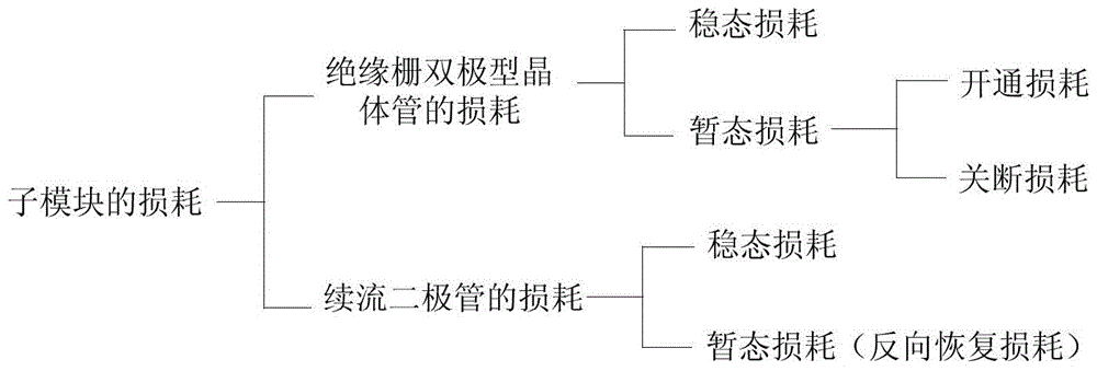
[0009] In view of the lack of effective current in the insulated gate bipolar transistor IGBT and the freewheeling diode FWD of the upper half bridge arm and the lower half bridge arm of the sub-module in the calculation of the loss of the converter mentioned in the above prior art, this paper The purpose of the invention is to provide a method for determining losses based on modular multi-level voltage source converters, the invention can reflect the losses and flexible direct current transmission of insulated gate bipolar transistors IGBT and freewheeling diodes FWD in sub-modules The relationship between the modulation factor, power factor, and active transmission power of the system visualizes complex issues

Method used


Image

  • A Loss Determination Method Based on Modular Multilevel Voltage Source Converter
  • A Loss Determination Method Based on Modular Multilevel Voltage Source Converter
  • A Loss Determination Method Based on Modular Multilevel Voltage Source Converter

Examples


Embodiment

[0097] Embodiment: The method of the present invention is described by taking the upper bridge arm of phase A of the converter in the inverter state as an example.

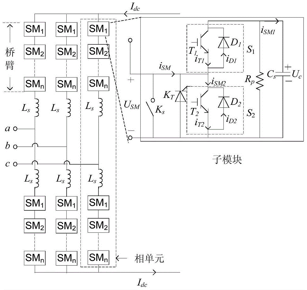
[0098] Step 1: Taking the upper bridge arm of phase A of the converter in the inverter state as an example, the composition of the converter and the reference direction of each current are as follows: figure 2 As shown, calculate the current of the controllable voltage source converter;

[0099] Step 1.1: Calculate the bridge arm current of the controllable voltage source converter;

[0100]

[0101] in:

[0102] I dc is the DC line current;

[0103] I m is the peak value of phase A current;

[0104] ω is the fundamental angular frequency;

[0105] is the angle at which phase A current lags A voltage.

[0106] Step 1.2: Calculate the current of the upper and lower tubes of the sub-module; the currents flowing through the upper and lower tubes of the sub-module are respectively:

[0107]

[0108] in ...


PUM


Abstract

The invention relates to the field of flexible direct current transmission (VSC‑HVDC), in particular to a method for determining loss of a flexible direct current converter based on modular multilevel technology. The method comprises the following steps: step 1: determining the current of the single-phase voltage source converter; step 2: determining the conduction loss of the voltage source converter; step 3: determining the switching loss of the voltage source converter ; Step 4: Determine the total loss of the three-phase voltage source converter. The method provided by the present invention effectively solves the upper half bridge arm insulated gate bipolar transistor IGBT / lower half bridge arm freewheeling diode FWD or the upper half bridge arm freewheeling diode FWD / lower half bridge arm insulated gate bipolar transistor of the converter sub-module The average current and effective current of the polar transistor IGBT can reflect the relationship between the loss of the insulated gate bipolar transistor IGBT and the freewheeling diode FWD in the sub-module and the modulation factor, power factor, and active transmission power of the flexible DC transmission system. Visualize complex problems.

Description

technical field [0001] The invention relates to a determination method in the field of flexible direct current transmission (VSC-HVDC), in particular to a loss determination method based on a modular multilevel voltage source converter. Background technique [0002] Flexible DC transmission technology has been widely used in various fields because of its flexibility in power transmission control. The flexible DC transmission technology based on modular multilevel converters is a new type of flexible DC transmission technology. There is no commutation failure, and it can supply power to the passive network without reactive power compensation and can flexibly control output. Flexible DC transmission technology is especially suitable for remote areas, islands and other small-capacity load power supply, new energy collection and grid connection, and urban power supply applications. Therefore, flexible direct current transmission technology has broad application prospects. [0...

Claims


Application Information

Patent Timeline
Patent Type & Authority Patents(China)
IPC IPC(8): H02M7/797
CPCH02M7/483Y02B70/10H02M1/0048H02M7/4835
Inventor 于鹏王海田汤广福孔明杨杰马巍巍夏方李小
Owner STATE GRID CORP OF CHINA
Learn More