

display device
A technology for a display device and a display part, which is applied to identification devices, instruments, optical elements, etc., can solve the problems of difficulty in visually identifying multiple operation parts and the operability of the display device is reduced, and achieves the effect of improving the operability and suppressing the widening
- Summary
- Abstract
- Description
- Claims
- Application Information
AI Technical Summary
Problems solved by technology
Method used
Image

Examples
Embodiment approach 1
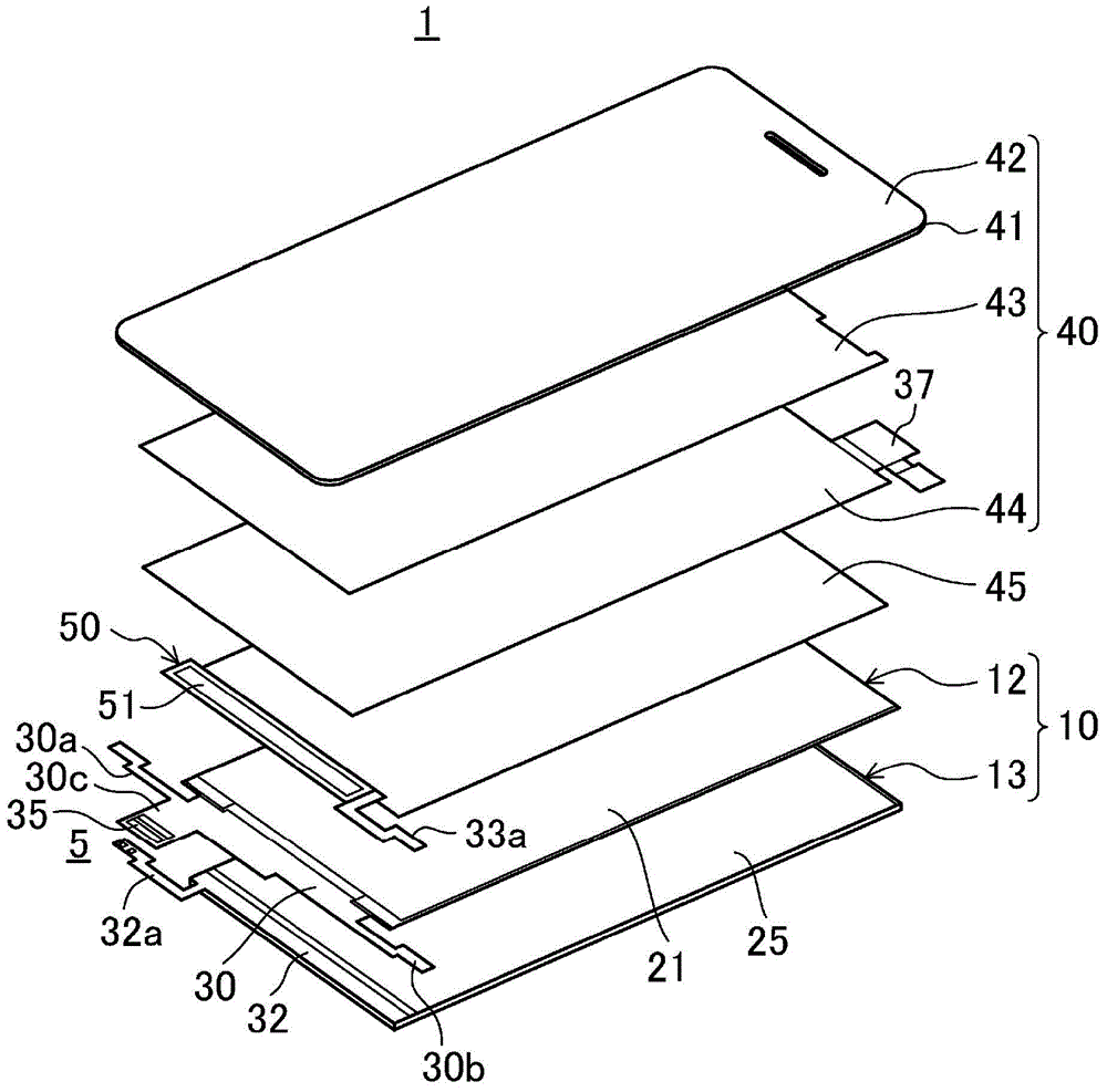
[0050] Figure 1 to Figure 17 Embodiment 1 of this invention is shown.
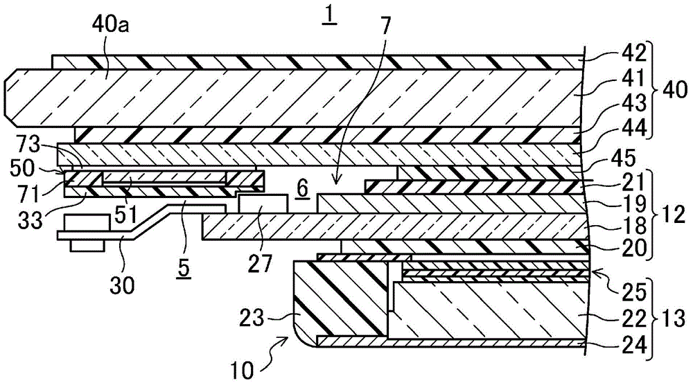
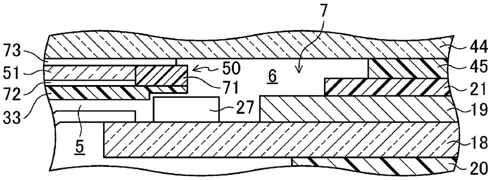
[0051] figure 1 It is a perspective view showing the configuration of main parts of the liquid crystal display device 1 of the first embodiment. figure 2 It is a cross-sectional view showing an enlarged side portion of the liquid crystal display device 1 . image 3 will be figure 2 A part of the cross-sectional view is shown enlarged. Figure 4 It is a perspective view showing the configuration of the light source unit 50 of the first embodiment. Figure 5 It is a plan view showing the appearance of the liquid crystal display device 1 .
[0052] in addition, Figure 15 It is a perspective view showing folded extension parts 30a, 30b, 32a, 33a. Figure 16 It is a perspective view showing the liquid crystal display device 1 after the extension parts 30a, 30b, 32a, and 33a are folded. Figure 17It is a perspective view which shows the insulating tape 55 which fixes extension part 30a, 30b, 32a, 33...
Embodiment approach 2
[0106] Figure 18 Embodiment 2 of this invention is shown.
[0107] Figure 18 It is a perspective view showing the configuration of the light source unit 50 according to the second embodiment. In addition, in each of the following embodiments, for the Figure 1 to Figure 17 The same reference numerals are attached to the same parts, and detailed descriptions thereof are partially omitted.
[0108] In this second embodiment, the structure of the light source unit 50 of the above-mentioned first embodiment is partially changed, and other structures are the same as those of the first embodiment.
[0109] Such as figure 1 and figure 2 As shown, the liquid crystal display device 1 includes: a panel laminate 10 having a liquid crystal display panel 12 as a display panel; and a substrate member 40 laminated on the panel laminate 10 .
[0110] Such as Figure 5 As shown, the liquid crystal display device 1 has: a display portion 2 for displaying by a liquid crystal display p...
Embodiment approach 3
[0130] Figure 19 and Figure 20 Embodiment 3 of this invention is shown.
[0131] Figure 19 It is an enlarged cross-sectional view showing the side portion of the liquid crystal display device 1 according to the third embodiment. Figure 20 will be Figure 19 A part of the cross-sectional view is shown enlarged.
[0132] In this third embodiment, the structure of the light source unit 50 of the above-mentioned first embodiment is partially changed, and other structures are the same as those of the first embodiment.
[0133] Such as Figure 19 As shown, the liquid crystal display device 1 includes: a panel laminate 10 having a liquid crystal display panel 12 as a display panel; and a substrate member 40 laminated on the panel laminate 10 .
[0134] Such as Figure 5 As shown, the liquid crystal display device 1 has: a display portion 2 for displaying by a liquid crystal display panel 12 ; and a non-display portion 3 formed around the display portion 2 . Such as Figu...
PUM
 Abstract
Description
Claims
Application Information