Melt spinning device and fiber shield

A technology of melt spinning and silk thread, which is applied in the field of thread cover, which can solve the problems of complicated operations and achieve the effect of preventing the thread from swinging

Active Publication Date: 2016-06-08
TMT MACHINERY INC
View PDF13 Cites 0 Cited by
  • Summary
  • Abstract
  • Description
  • Claims
  • Application Information

AI Technical Summary

Problems solved by technology

However, in this case, the multifilaments that should be split into two for each multifilament become one while traveling in the elongated barrel, and there is a possibility that the work of splitting the plurality of monofilaments into two for each multifilament becomes complicated. to worry about

Method used


Image

  • Melt spinning device and fiber shield
  • Melt spinning device and fiber shield
  • Melt spinning device and fiber shield

Examples


Embodiment Construction

[0036] The preferred embodiment of the present invention will be described below.

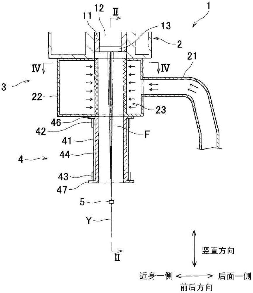
[0037] Such as figure 1 , figure 2 As shown, the melt spinning device 1 of the present embodiment includes a spinning beam 2 ("spinning section" in the present application), a cooling device 3, a plurality of extension tubes 4 ("thread cover" in the present invention), and an oil guide 5 (the "thread guide" of the present invention) and the like. In addition, the following figure 1 The direction indicated in etc. is the vertical direction.

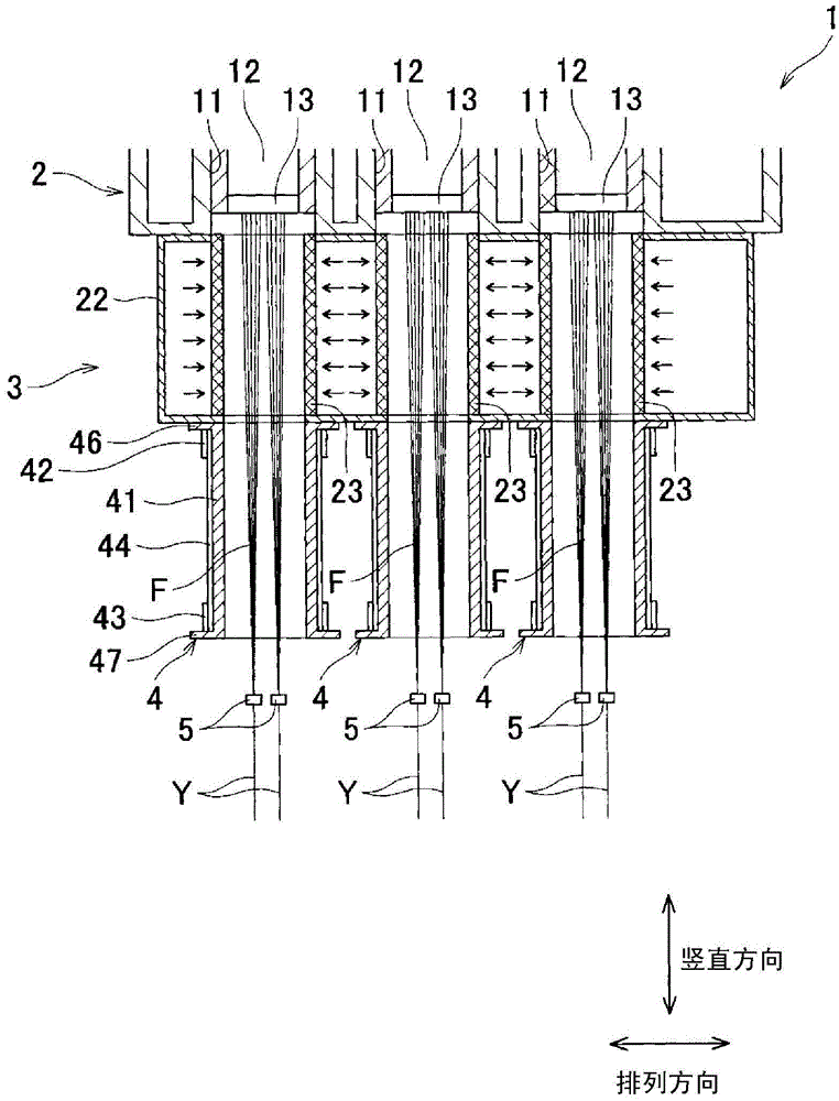
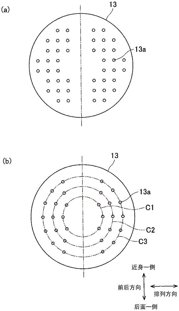
[0038] The spinning beam 2 includes a plurality of module housings 11. A spinning module 12 is arranged in each module housing 11. In the spinning module 12, a polymer line (not shown) connected to the module housing 11 is used to meter and pressure-feed molten polymer such as polyester. A spinneret 13 is provided at the lower end of the spinning assembly 12. Among them, the multiple spinnerets 13 of the spinning beam 2 pass along and figure 1 Are arranged ...


PUM

PropertyMeasurementUnit
diameteraaaaaaaaaa
lengthaaaaaaaaaa

Abstract

The invention relates to a melt spinning device and a fiber shield. Fiber division operation that a plurality of single fibers passing through inner space of the fiber shield are distributed to each fiber can be easily carried out. An opening component (41d) is formed in a side wall of a cylindrical component (41) for distributing the plurality of single fibers (F) passing through the inner space (41a) to each fiber (Y). The opening component (41d) extends from a position right below a flange portion (46) arranged at an upper end of the cylindrical component (41) to a lower end of the cylindrical component (41). An open-close component (44) is arranged at an outer peripheral face (41c) of the cylindrical component (41) and is capable of performing peripheral slide on the outer peripheral face (41c) along the cylindrical component (41). The open-close component (44) slides to open and close the opening component (41d).

Description

Technical field [0001] The present invention relates to a melt spinning device and a silk thread cover arranged in the melt spinning device. Background technique [0002] In the melt spinning device described in Patent Document 1, the single fiber group (corresponding to the "multiple single fiber" of the present invention) spun from the spinning beam (corresponding to the "spinning section" of the present invention) is arranged in The cooling device below the spinning beam is cooled by blowing cooling air. In addition, the single fiber group cooled and solidified by the cooling device is conveyed to the winding device after the oil agent is applied by the oil agent applying device arranged below the cooling device. In addition, in Patent Document 1, an extension tube (corresponding to the "wire cover" of the present invention) is arranged between the cooling device and the oil application device. The single fiber group blown with cooling air by the cooling device is solidified...

Claims


Application Information

Patent Timeline
Patent Type & Authority Applications(China)
IPC IPC(8): D01D5/08D01D11/02D01D5/088
CPCD01D5/08D01D5/088D01D11/02
Inventor 乾俊哉
Owner TMT MACHINERY INC
Why Eureka
Try Eureka