Compression tool for fastening spring-back stop ring to piston rod of shock absorber of motor vehicle

A technology of limit ring and piston rod, applied in the direction of shock absorber, spring/shock absorber, shock absorber, etc., can solve problems such as difficult distinction, and achieve the effect of simplifying targeted control

Pending Publication Date: 2022-07-29
ZF FRIEDRICHSHAFEN AG
View PDF1 Cites 0 Cited by
  • Summary
  • Abstract
  • Description
  • Claims
  • Application Information

AI Technical Summary

Problems solved by technology

[0015] Such a non-optimally compressed piston rod-rebound stop ring unit can only be distinguished with difficulty from an optimally formed piston rod-rebound stop ring unit

Method used


Image

  • Compression tool for fastening spring-back stop ring to piston rod of shock absorber of motor vehicle
  • Compression tool for fastening spring-back stop ring to piston rod of shock absorber of motor vehicle
  • Compression tool for fastening spring-back stop ring to piston rod of shock absorber of motor vehicle

Examples


Embodiment Construction

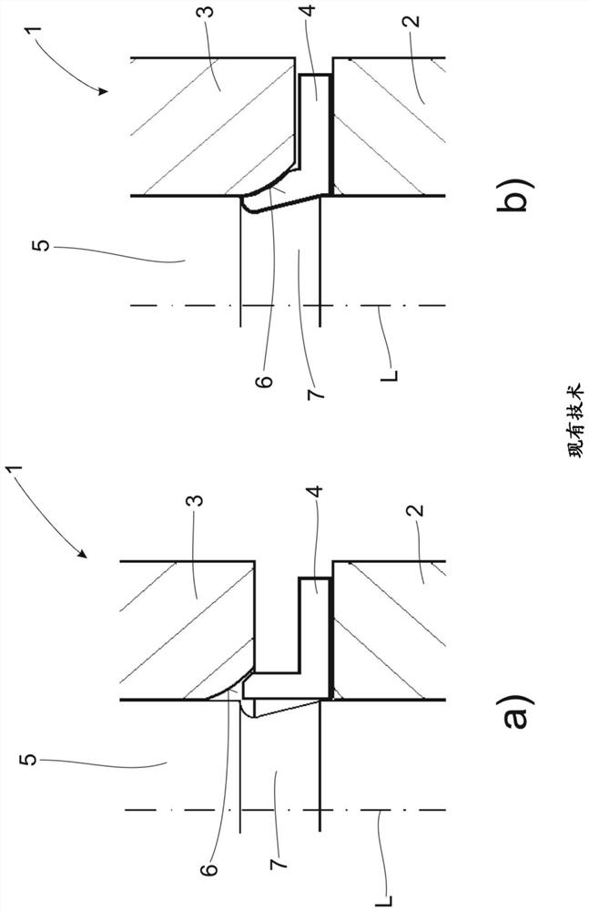
[0035] figure 1 The figures a) and b) show a pressing tool 1 implemented according to the prior art for fastening the rebound stop ring 4 on the piston rod 5 of the shock absorber. Here, illustration a) shows the initial position of the first workpiece 2 , the second workpiece 3 , the piston rod 5 and the rebound stop ring 4 shortly before the start of the tightening process. In this case, the press-in surface 6 of the second workpiece 3 is convex.

[0036] On the other hand, illustration b) shows the final state of the fastening process, after which the first workpiece 2 and the second workpiece 3 are moved coaxially to each other by fastening means not explicitly shown here to the extent that , the distance between the two workpieces 2, 3 is reduced to a final dimension defined by the system pressure of the fastening device. The rebound stop ring 4 is pressed in sections into a circumferential groove 7 formed on the piston rod 5 and surrounding the piston rod 5 , thereby f...


PUM


Abstract

The invention relates to a pressing tool 1 for fastening a spring-back stop ring 4 to a piston rod 5 of a shock absorber, comprising a first workpiece 2 and a second workpiece 3, the first workpiece 3 axially supporting the spring-back stop ring 4 and the second workpiece 3 being displaced axially in the direction of the first workpiece 2 relative to a longitudinal extension axis L during the fastening process, the spring-back limiting ring (4) is partially pressed into a circumferential groove (7) formed on the piston rod (5) by means of the pressing surface (6) of the second workpiece, as a result of which a non-separable, form-fitting connection is formed between the piston rod (5) and the spring-back limiting ring (4). The invention is characterized in that the press-in surface 6 of the second workpiece 3 is designed as a convexly shaped ring, the convexly shaped ring being partially separated by at least one recess 8.

Description

technical field [0001] The invention relates to a pressing tool according to the preamble of claim 1 for fastening a rebound stop ring on a piston rod of a motor vehicle shock absorber. Background technique [0002] Pressing tools for fastening a rebound stop ring on a piston rod and thus for providing a piston rod-rebound stop ring-structural unit for motor vehicle shock absorbers are well known from the automotive industry. [0003] The document DE 10 2013 220 627 B3, for example, shows a universal pressing tool for automatic fastening devices. This pressing tool comprises a first workpiece and a second workpiece, wherein the first workpiece is configured to axially support the rebound stop ring, and the second workpiece is pivoted relative to the longitudinal extension axis L in the direction of the first workpiece by the fastening device is displaced in the direction of displacement, and by means of the press-in surface of the second workpiece, the rebound stop ring is ...

Claims


Application Information

Patent Timeline
Patent Type & Authority Applications(China)
IPC IPC(8): B25B27/00B25B27/02F16F9/32
CPCB25B27/0035B25B27/02F16F9/3271B23P11/005F16F2230/007F16F2230/0041F16F2226/04F16F9/3221
Inventor S·霍奇格桑F·卡尔
Owner ZF FRIEDRICHSHAFEN AG
Why Eureka
Try Eureka