Smoke evacuation system for continuously removing gas from a body cavity

a gas delivery system and continuous technology, applied in the field of surgical gas delivery systems, can solve problems such as requiring the surgical team to evacuate smoke, causing smoke to be released, and delay in surgery,

Active Publication Date: 2018-08-09
CONMED CORP
View PDF3 Cites 176 Cited by
  • Summary
  • Abstract
  • Description
  • Claims
  • Application Information

AI Technical Summary

Benefits of technology

[0013]The subject invention is directed to a new and useful system for delivering insufflation gas to a body cavity of a patient during an endoscopic or laparoscopic surgical procedure. In one embodiment of the invention, the system includes an insufflation conduit for delivering an essentially continuous flow of insufflation gas to the body cavity of a patient at a variable flow rate through a flow path that communicates with a pneumatically sealed trocar which prevents over-pressurization of the body cavity, and an insufflator for driving gas flow through the insufflation conduit at a given driving pressure, wherein the gas flow rate through the insufflation conduit will vary depending upon body cavity pressure. This system further includes a flow meter communicating with the insufflation conduit and located between the insufflator and the body cavity for continuously measuring gas flow through the insufflation conduit, and a processor for determining a body cavity pressure corresponding to a given driving pressure based upon a gas flow measurement from the flow meter.
[0017]In another embodiment of the invention, the system includes an insufflation conduit for delivering an essentially continuous flow of insufflation gas to the body cavity at a flow rate through a flow path that communicates with a pneumatically sealed trocar which prevents over-pressurization of the body cavity, and an insufflator for driving gas flow through the insufflation conduit at a driving pressure, wherein the system can be configured so that either the gas flow rate through the insufflation conduit or the driving pressure required to maintain the specified flow rate can vary depending upon body cavity pressure.
[0024]In another embodiment of the invention, an outlet side of the pump communicates with the inlet flow path, downstream from the insufflation unit. Here, a first valve is associated with the outlet side of the pump and is controlled by the processor to bleed off gas to atmosphere, and / or a second valve also located on the outlet side of the pump is controlled by the processor to allow new insufflation gas to be driven into the inlet flow path. This embodiment of the invention allows the insufflation unit to augment to inlet flow and maintain smoke evacuation.
[0030]More particularly, the processor controls the pump in such a manner so that clean gas is delivered to the body cavity by the pump at a gas flow rate that is equal to the gas flow rate at which smoky gas is removed from the body cavity by the pump to maintain the desired insufflation pressure, or at a gas flow rate that is greater than or less than the gas flow rate at which smoky gas is removed from the body cavity by the pump, in the event of an under-pressure condition or an over-pressure condition in the body cavity. It is envisioned that the system could be configured with a valve on the inlet side of the pump that would be controlled by the processor to draw in more gas from atmosphere and / or a valve on the outlet side of the pump that would be controlled by the processor to bleed off some of the gas flow to atmosphere in order to better adjust the flow rate. It should be understood that while the flow of gas throughout this system is essentially continuous, there may be circumstances in which the insufflation or gas delivery flow rate and / or the evacuation or gas removal flow rate could temporarily drop to 0 L / min, in order to prevent extreme under or over pressure conditions in the system.

Problems solved by technology

These devices are used to cut and / or coagulate tissue during a surgical procedure, and typically give off smoke during this process.
The smoke can cloud the vision of the endoscopic camera, leading to delays in surgery or requiring the surgical team to evacuate that smoke.

Method used


Image

  • Smoke evacuation system for continuously removing gas from a body cavity
  • Smoke evacuation system for continuously removing gas from a body cavity
  • Smoke evacuation system for continuously removing gas from a body cavity

Examples


Embodiment Construction

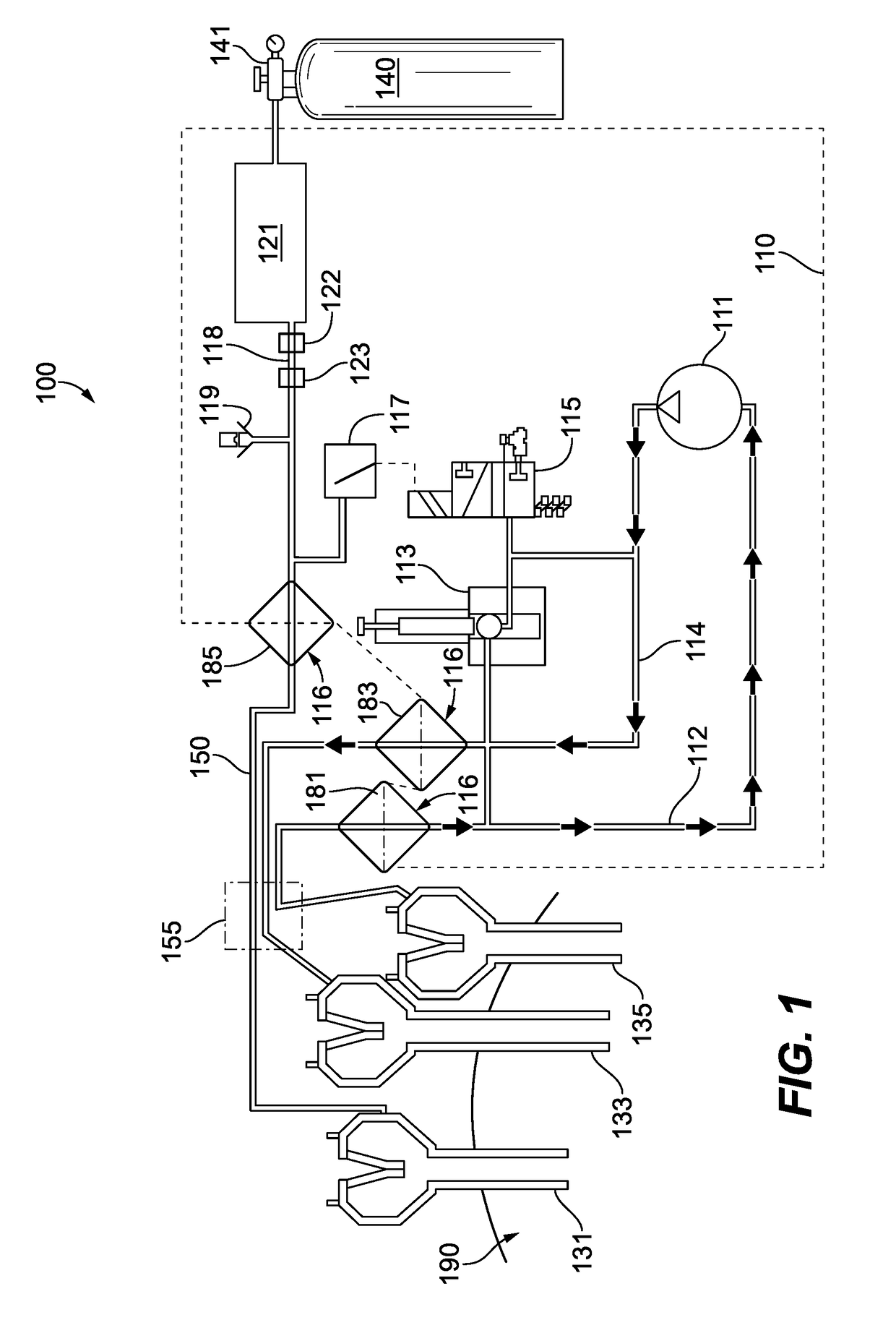
[0043]Referring now to the drawings, wherein like reference numerals identify similar structural elements or features of the subject invention, there is illustrated in FIG. 1 a multimodal surgical gas delivery system constructed in accordance with a preferred embodiment of the subject invention and designated generally by reference numeral 100. As described in more detail below, the gas delivery system 100 is designed for multimodal operation to facilitate insufflation of a body cavity, smoke evacuation from the body cavity and / or gas recirculation through an access port communicating with the body cavity. In addition, the surgical gas delivery system 100 is configured to maintain body cavity pressure when suction is used within the body cavity during a surgical procedure to remove solid debris, liquids and gases from the body cavity.

[0044]As shown in FIG. 1, the gas delivery system 100 is adapted to function with three surgical access devices or trocars (131, 133, 135) that are in ...


PUM


Abstract

An evacuation system for continuously removing gas from a body cavity of a patient during an endoscopic surgical procedure is disclosed, which includes an inlet flow path leading to a first trocar communicating with the body cavity through which an essentially continuous flow of gas is delivered to the body cavity, an outlet flow path leading from a second trocar communicating with the body cavity though which an essentially continuous flow of gas is removed from the body cavity, a pump communicating at least with the outlet flow path for removing an essentially continuous flow of gas from the surgical cavity, and a processor operatively associated with the pump for controlling at least the essentially continuous flow of gas from the body cavity.

Description

CROSS-REFERENCE TO RELATED APPLICATION[0001]The subject application claims is a continuation-in-part of U.S. patent application Ser. No. 15 / 812,649 filed Nov. 14, 2017, which claims the benefit of priority to U.S. Provisional Patent Application Ser. No. 62 / 421,480 filed Nov. 14, 2016, the disclosures of which are herein incorporated by reference in their entireties.BACKGROUND OF THE INVENTION1. Field of the Invention[0002]The subject invention relates to surgical gas delivery systems, and more particularly, to multimodal gas delivery systems for surgical insufflation, smoke evacuation and / or recirculation, which is also configured for continuous pressure monitoring of a body cavity by way of a continuous flow of gas to and / or from a body cavity.2. Background of the Related Art[0003]Minimally invasive surgical techniques such as endoscopic and laparoscopic surgical procedures have become increasingly common. Benefits of such procedures include reduced trauma to the patient, reduced o...

Claims


Application Information

Patent Timeline
Patent Type & Authority Applications(United States)
IPC IPC(8): A61M13/00A61B17/34
CPCA61M13/006A61B17/3474A61B2218/008A61M2205/75A61B2017/00221A61B17/3421A61M1/0031A61M2205/70A61M2205/33A61B1/3132A61B2017/00199A61M2205/3334A61M2205/3344A61M2205/3569A61M2205/3584A61M2205/3592A61M2205/502A61M2210/1021A61M1/74A61B1/015
Inventor SILVER, MIKIYA
Owner CONMED CORP
Why Eureka
Try Eureka