Dual purpose dryers for high flow

a dryer and high-flow technology, applied in the direction of braking system, separation process, braking components, etc., can solve the problems of air dryers that cannot meet the demands of these systems, air dryers that cannot provide continuous air, and loss of function, so as to prevent over-pressurization of the compressor discharge line

Active Publication Date: 2015-11-10
BENDIX COMML VEHICLE SYST LLC
View PDF8 Cites 0 Cited by
  • Summary
  • Abstract
  • Description
  • Claims
  • Application Information

AI Technical Summary

Benefits of technology

[0006]The present disclosure sets forth a system and method that configures a two dryer air system based on one or more of engine load and / or a vehicle parked condition. For example, a large capacity compressor having an inlet in communication with a turbo-charged intake of a vehicle may have an output, during certain operations in over the road applications, that exceeds the capacity of any given single (e.g, stand alone) air dryer. This can occur, for example, during high engine RPMS when the turbocharger is near maximum boost. To accommodate the high output of the large capacity compressor during such times, two air dryers are connected in parallel to prevent over-pressurization of the compressor discharge line. The two air dryers can be sized to accommodate the maximum output of the large capacity compressor when connected in parallel. The system and method of the present disclosure is also configured to alternately cycle each air dryer between a drying mode and a purging mode during lower compressor output. This configuration allows continuous flow without requiring four air dryers, alternating two at a time, for situations such as bulk unloading, etc.

Problems solved by technology

Known air dryers cannot meet the demands of these systems.
More specifically, a desiccant material in the air dryer becomes overwhelmed and saturated, ultimately resulting in loss of function.
However, when used in parallel, the air dryers cannot provide continuous air because they will need to be taken offline together to be purged.
This adds complexity and cost to the system, and requires additional onboard space for the extra components.

Method used


Image

  • Dual purpose dryers for high flow
  • Dual purpose dryers for high flow
  • Dual purpose dryers for high flow

Examples


Embodiment Construction

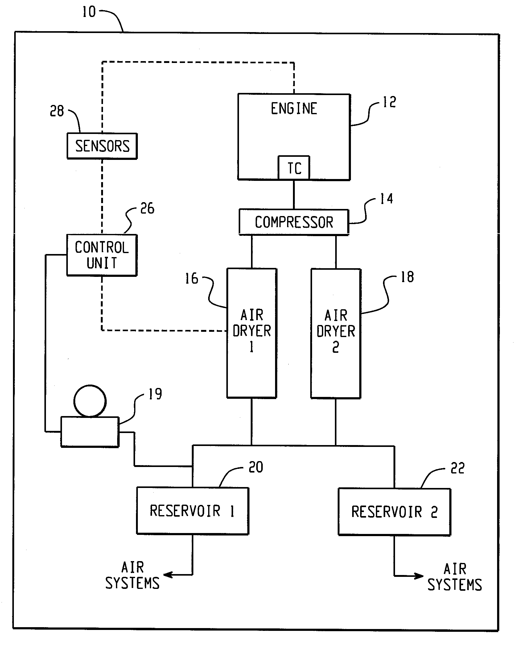
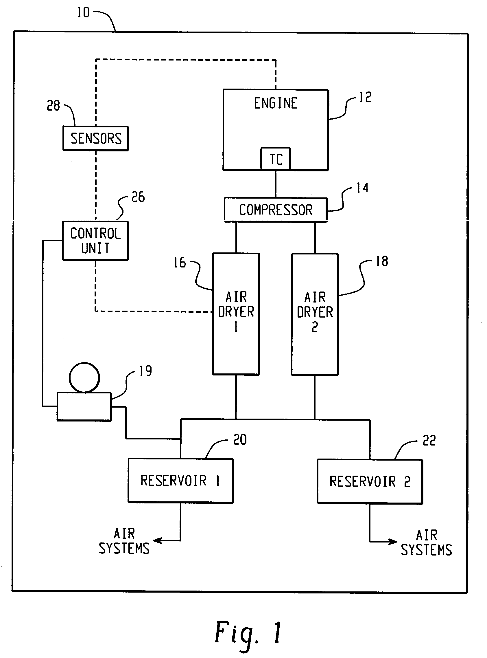
[0016]With reference to FIG. 1, an exemplary air dryer system in accordance with the present disclosure is illustrated schematically as part of a vehicle 10. The vehicle 10 includes an engine 12 including a turbocharger TC, such as a turbocharged diesel engine of a truck or the like, a compressor 14 pneumatically coupled to the turbocharger TC, first and second air dryers 16 and 18 coupled to the outlet of the compressor 14, and first and second reservoirs 20 and 22 for storing compressed, dried air. In the illustrated embodiment, the compressor 14 is a high output compressor including a turbo inlet configured to receive pressurized air from the turbocharger TC. During times of high boost, the mass flow rate of the air received by the compressor is relatively high, while during times of no or low boost the mass flow rate is relatively low. Accordingly, the output of the compressor 14 flowing to the air dryers 16 and 18 is highest during times of high turbocharger boost and lowest du...


PUM


Abstract

A system and method of controlling an air dryer system having first and second air dryers configured to receive compressed air from a compressor, such as a compressor of a vehicle, including operating the first and second air dryers in a first mode corresponding to a high flow mode wherein the first and second air dryers are connected in parallel with the air compressor, monitoring a condition related to a low compressor output state, and operating the first and second air dryers in a second mode corresponding to a continuous flow mode when the low compressor output state is detected.

Description

BACKGROUND[0001]The present invention relates to compressed fluid systems for vehicles. It finds particular application in conjunction with systems utilizing a pair of air dryers for removing moisture from compressed air and will be described with particular reference thereto. It will be appreciated, however, that the invention is also amenable to other like applications.[0002]Transit coaches and air-assisted bulk-off load units are illustrative of compressed air systems used for operating brakes and accessories (e.g., tire inflation systems) of vehicles (e.g., heavy-duty trucks, tractors, trailers, or tractor-trailer combinations). Known air dryers cannot meet the demands of these systems. More specifically, a desiccant material in the air dryer becomes overwhelmed and saturated, ultimately resulting in loss of function.[0003]Continuous flow air dryers are used for air brake vehicle applications where high air use calls for extended charging times and high compressor duty cycles. C...

Claims


Application Information

Patent Timeline
Patent Type & Authority Patents(United States)
IPC IPC(8): B01D53/04B60T17/00B01D53/26
CPCB60T17/004B01D53/0454B01D53/261B01D2257/80B01D2259/4566
Inventor EBERLING, CHARLES E.HOFFMAN, FRED W.RIPLEY, JOHN V.NECHVATAL, ROBERT J.
Owner BENDIX COMML VEHICLE SYST LLC
Why Eureka
Try Eureka