Automated balloon catheter fluid purging system

a technology of fluid purging system and balloon catheter, which is applied in the field of automatic balloon catheter fluid purging system, can solve the problems of increasing the volume of the balloon chamber, affecting the operation of the catheter, and unable to meet the needs of medical devices, so as to optimize the gas escape path, optimize the rate of pressure rise, and improve the effect of pressure ris

Active Publication Date: 2016-10-18
CRYOFOCUS MEDTECH (SHANGHAI) CO LTD
View PDF3 Cites 0 Cited by
  • Summary
  • Abstract
  • Description
  • Claims
  • Application Information

AI Technical Summary

Benefits of technology

[0020]c. prevent over-pressurization by purging pressurized fluid and relieving compressed fluid (through the use of a solenoid valve as an exhaust valve);
[0023]Mounting the relief valve directly to the catheter also provides other advantages. First, the rate of pressure rise due to a constant gas leakage within an optimized or smaller balloon chamber is faster as predicted by the natural gas law. The natural gas law dictates that pressure increases linearly with additional mass gained. For larger balloon chambers, the rate of pressure rise is slower for the same amount of mass added or gas leaked into the balloon chamber. As a result, the present system can detect and respond earlier when encountering an abnormal pressure spike situation. Second, mounting the relief valve directly to the catheter optimizes the gas escape path. Leaked gas from the distal end has to travel to the relief valve to be relieved. Shortening this passage reduces balloon fluid resistance and allows the leaked gas to push its way into the relief valve more quickly. This also benefits the response time of the system.
[0024]The present invention allows the system to be more sensitive in detecting gas leakage. This is possible because the present invention is more forgiving of user errors and component tolerance. The present invention allows the user to fill and pressurize the balloon chamber right at, or near, the cracking pressure of the relief valve. Preloading the system pressure in this manner eliminates the issues of pressure tolerance of the relief valve, and user induced errors. A small amount of fluid leaked across the relief valve during the balloon filling process is tolerable because the purging tube has an empty volume that can be used to store liquid without triggering the pressure switch. A gas leakage into the balloon chamber from the catheter delivery system will instantly escape the relief valve and be detected by the pressure sensor.

Problems solved by technology

However, this arrangement is not practical for medical device applications.
This will result in greater volume added to the balloon chamber, making it more difficult to evacuate it of trapped air.
Having a larger volume will make the air evacuation process more time-consuming and difficult.
In addition, a larger volume requires more fluid to fill.
As a result, this setup is less efficient and increases overall procedure time.
Mounting the pressure switch and the exhaust solenoid valve directly to the catheter would solve the above issues, but would make the assembly very cumbersome to handle.
This setup is also expensive since the two components are disposable.
Regardless of the setups described above, a typical industrial purging system is not sensitive and quick to detect pressure spikes within the system because the detection / switching pressure of the pressure sensor has to be set at a value above the working pressure or balloon pressurization pressure.
First, pressurization of the balloon chamber is normally performed manually, resulting in variations in the pressure generated.
Otherwise, the system might trigger a false alarm.
This will delay the response time, making the system less responsive in detecting gas leakage.
However, reducing system response time is very critical in maximizing system performance.
Catheters that carry gas through a delivery system placed inside the human body can potentially break and leak gas.
An automated computer controlled purging system is needed because a manual monitoring and purging system does not provide the reliability, consistency, and instantaneous response needed to safeguard against abnormal pressure rises, and especially when there is a gas leakage from the gas delivery line.
Pressurized gas can rapidly fill up a small confined balloon volume and cause significant pressure rise in short period of time.
a. Internal pressure adds stress on the component and causes it to expand. Over-pressuring the balloon, for example, can inflate the balloon to be larger than originally intended. This could stretch the patient's arterial wall beyond elastic limit and cause permanent damage.
b. High internal pressure will stress the material to its rupture point where it will burst open and release its fluid.
c. Unwanted fluid (such as pressurized gas, cryogen, etc.) can be released into the patient and cause trauma and even death.
A bursting balloon can cause physical damage to its surrounding (i.e., arterial wall) as the high pressure ruptures the balloon wall, pressing the torn material outward, and further stretching the surrounding wall, creating damages.
Finally, detecting pressure is more cost-effective than detecting flow / leakage rate or fluid accumulation level, which requires a bulkier and more expensive flow meter or level indicator.

Method used


Image

  • Automated balloon catheter fluid purging system
  • Automated balloon catheter fluid purging system
  • Automated balloon catheter fluid purging system

Examples


Embodiment Construction

[0032]The following detailed description is of the best presently contemplated modes of carrying out the invention. This description is not to be taken in a limiting sense, but is made merely for the purpose of illustrating general principles of embodiments of the invention. The scope of the invention is best defined by the appended claims.

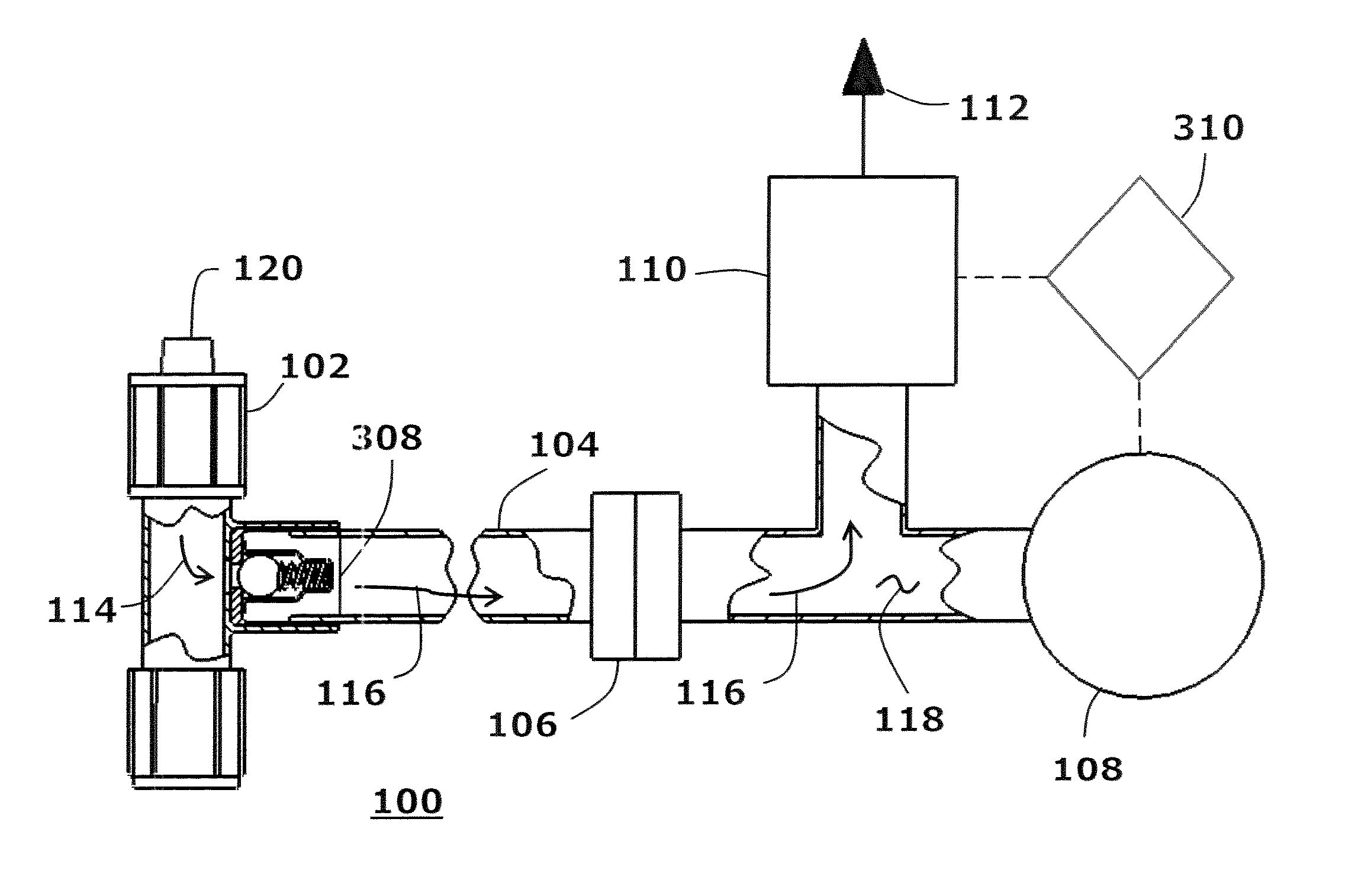
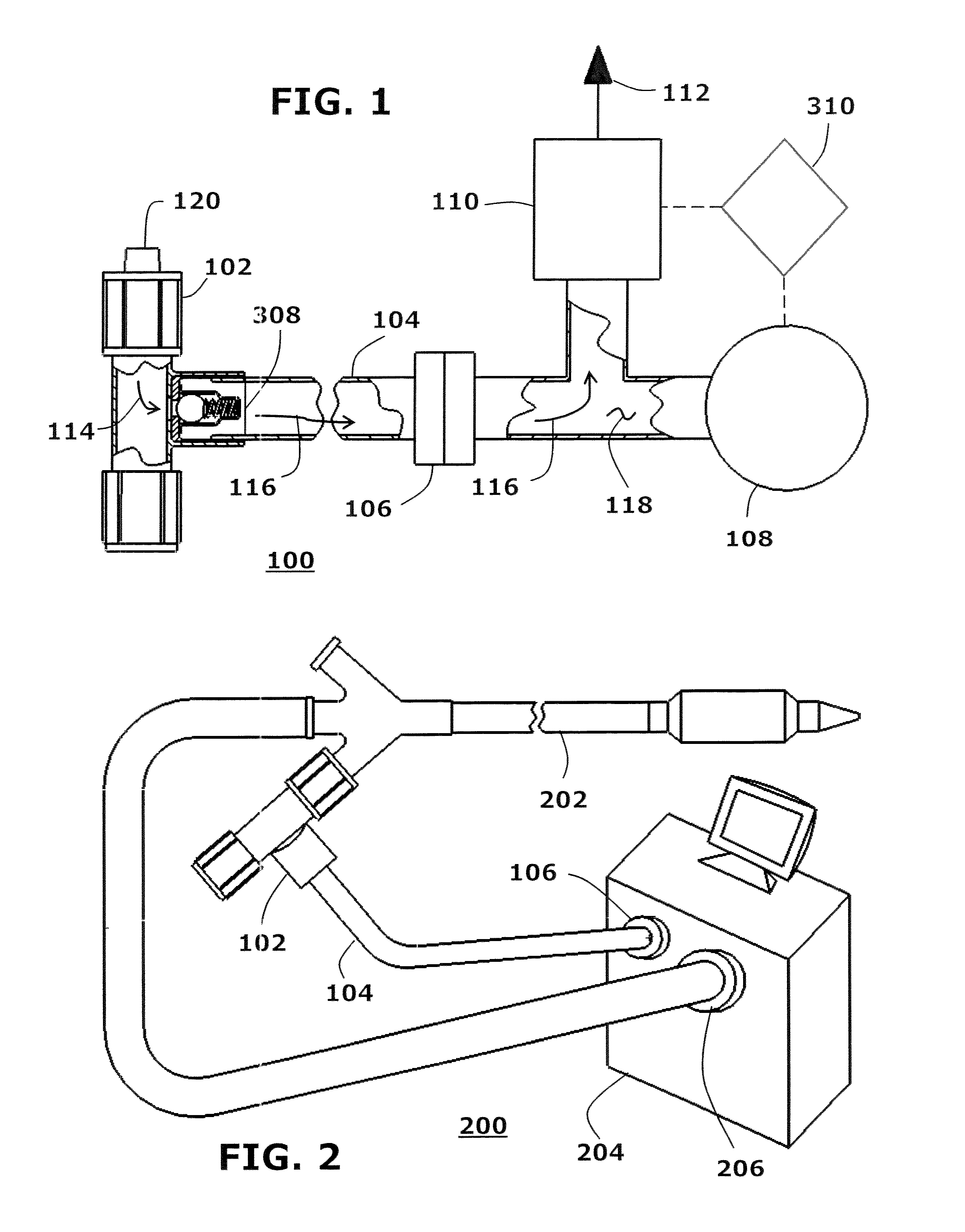
[0033]Referring to FIG. 1, the present invention provides a fluid purging system 100 that receives incoming fluid 114 through an inlet port 120 of a relief valve 102. The relief valve 102 is a standard spring-energized relief valve having a differential cracking pressure pre-set within the pressure range of 20 to 750 psig. The relief valve 102 acts like a check valve by allowing flow in one direction and restricting flow in the reverse direction. Flow through the relief valve 102 is possible when the internal fluid pressure rises above the cracking pressure of the relief valve 102. For the present invention, the cracking pressure can be set within...


PUM


Abstract

A fluid purging system has a spring-energized relief valve having an inlet port that is coupled to a fluid chamber to receive incoming fluid, and an outlet port through which incoming fluid is relieved. The outlet port is fluidly coupled to a pressurized chamber. The fluid purging system also includes an electro-mechanical pressure switch, and an electrically operated solenoid valve which functions as a pressure exhaust valve. The pressure switch and the solenoid valve are in fluid communication with the pressurized chamber.

Description

BACKGROUND OF THE INVENTION[0001]1. Field of the Invention[0002]The present invention relates to catheter systems, and in particular, to an automated balloon catheter fluid purging system.[0003]2. Description of the Related Art[0004]A typical industrial fluid purging system normally uses a pressure sensor (i.e. pressure switch, pressure transducer, etc.) to detect the fluid pressure within the pressurized chamber, and relieves high pressure directly from the pressurized chamber through an exhaust valve. This typical industrial fluid purging system does not incorporate a relief valve ahead of the pressure sensor, thereby making it simpler to implement. However, this arrangement is not practical for medical device applications. Specifically, the placements of these two components are critical. If the two components (pressure sensor and exhaust valve) are mounted within a system enclosure, a long fluid connection line is necessary. This will result in greater volume added to the balloo...

Claims


Application Information

Patent Timeline
Patent Type & Authority Patents(United States)
IPC IPC(8): A61B18/02A61B18/00A61M25/10A61M1/10
CPCA61B18/02A61M1/10A61M25/10186A61B2018/0022A61B2018/0212A61B2018/0262Y10T137/7761A61M60/274
Inventor DUONG, THACH BUUZENG, MIN FRANK
Owner CRYOFOCUS MEDTECH (SHANGHAI) CO LTD
Why Eureka
Try Eureka