System and Method for Monitoring and Controlling Underground Drilling

a technology of monitoring and controlling the operation of underground drilling, applied in the field of underground drilling, can solve the problems of premature failure of the various components of the drill string, premature dulling of the drill bit, and substantial vibration and shock in the drill string, and achieve the effect of reducing the difference between the measured vibration and the measured vibration

Active Publication Date: 2011-08-04
APS TECH
View PDF84 Cites 183 Cited by
  • Summary
  • Abstract
  • Description
  • Claims
  • Application Information

AI Technical Summary

Benefits of technology

[0056]In one embodiment, the invention encompasses a method, which may be computer implemented, of monitoring the operation of a drill string drilling into an earthen formation so as to form a bore hole using a drill bit, comprising the steps of: (a) drilling a bore hole having a first diameter in the earthen formation by rotating the drill bit at a first rotary speed and applying a first weight on the bit; (b) making a determination of the value of the first rotary speed at which the drill bit rotates; (c) making a determination of the value of the first weight on the bit; (d) making a determination of the value of the first diameter of the bore hole; (d) measuring vibration in the drill string at least one predetermined location along said drill string while rotating said drill bit at said first speed and applying the first weight on the bit; (e) using a finite element model of the drill string to predict the vibration in the drill string at the at least one predetermined location based on the determined valu

Problems solved by technology

The drilling environment, and especially hard rock drilling, can induce substantial vibration and shock into the drill string.
Such vibration can result in premature failure of the various components of the drill string, premature dulling of the drill bit, or may cause the drilling to be performed at less than optimum conditions.
For example, although reducing the downhole force applied to the drill bit, commonly referred to as the “weight on bit” (“WOB”) or the rotary speed of the drill bit may reduce vibration, it may also reduce drilling efficiency.
In particular, drill bits are typically designed for a predetermined range of rotary speed and WOB and do not perform as effectively if operated outside this range in order to avoid excessive vibration.
Moreover, operating the drill bit away from its design point can reduce the service life of the drill bit.
For example, very high axial vibration can result in a loss of contact between the drill bit and the surface being drilled.
Lateral vibration often arises because the drill string rotates in a bent condition.
Often, the bit will over-speed as it unwinds.
However, notwithstanding the availability of such data, obtaining the optimal rate of penetration is a difficult endeavor.
Formations may change, bits may dull, mud weight and the hydraulics may change.
Drill collars may also have features, such as electronics hatches, upsets and cutout, that create a rotating imbalance.
In addition, drill collars that become bent in service cr

Method used


Image

  • System and Method for Monitoring and Controlling Underground Drilling
  • System and Method for Monitoring and Controlling Underground Drilling
  • System and Method for Monitoring and Controlling Underground Drilling

Examples


Embodiment Construction

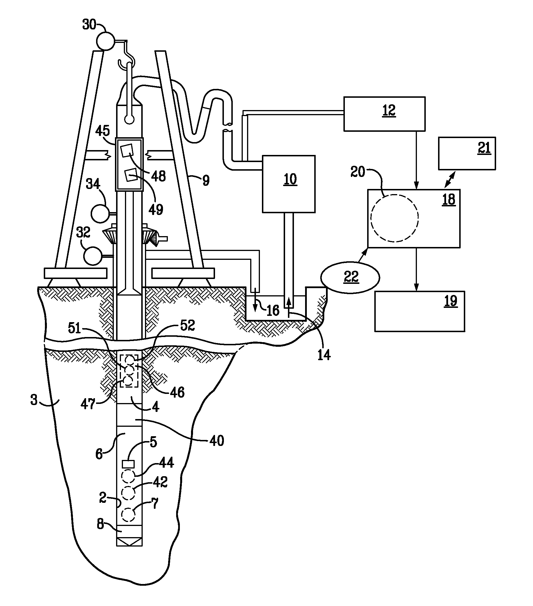
[0079]As shown in FIG. 4, drill rigs typically comprise a derrick 9 that supports a drill string 4. A drill bit 8 is coupled to the distal end of a bottomhole assembly 6 of the drill string 4. A prime mover (not shown), such as a top drive or rotary table, rotates the drill string 4 so as to control the rotational speed (RPM) of, and torque on, the drill bit 8. As is conventional, a pump 10 pumps a fluid 14—typically referred to as drilling mud—downward through an internal passage in the drill string. After exiting at the drill bit 8, the returning drilling mud 16 flows upward to the surface through an annular passage formed between the drill string 4 and the bore hole 2 in the earthen formation 3. A mud motor 40, such as a helicoidal positive-displacement pump—sometimes referred to as a “Moineau-type” pump—may be incorporated into the bottomhole assembly 6 and is driven by the flow of drilling mud 14 through the pump. A helicoidal positive-displacement pump is described more fully ...


PUM


Abstract

A system and method for monitoring underground drilling in which vibration is monitored by creating a model of the drill string using finite element techniques or finite difference techniques and (i) predicting vibration by inputting real time values of operating parameters into the model, and then adjusting the model to agree with measured vibration data, (ii) predicting the weight on bit and drill string and mud motor speeds at which resonance will occur, as well as when stick-slip will occur, so that the operator can avoid operating regimes that will result in high vibration, (iii) determining vibration and torque levels along the length of the drill string based on the measured vibration and torque at one or more locations, (iv) determining the remaining life of critical components of the drill string based on the history of the vibration to which the components have been subjected, and (v) determining the optimum drilling parameters that will avoid excessive vibration of the drill string.

Description

FIELD OF THE INVENTION [0001]The present invention relates to underground drilling, and more specifically to a system and a method for monitoring and controlling the drilling operation, especially operation related to drill string vibration, so as to achieve optimum performance and life from the drill string.BACKGROUND OF THE INVENTION AND RELATED ART [0002]Underground drilling, such as gas, oil, or geothermal drilling, generally involves drilling a bore through a formation deep in the earth. Such bores are formed by connecting a drill bit to long sections of pipe, referred to as a “drill pipe,” so as to form an assembly commonly referred to as a “drill string.” The drill string extends from the surface to the bottom of the bore.[0003]The drill bit is rotated so that the drill bit advances into the earth thereby forming the bore. In rotary drilling, the drill bit is rotated by rotating the drill string at the surface. Piston-operated pumps on the surface pump high-pressure fluid, re...

Claims


Application Information

Patent Timeline
IPC IPC(8): E21B44/00E21B47/00G06F19/00G06F17/18G06F17/10
CPCG05B13/048G05B23/0243G05B2219/24075G05B2219/2616G01M13/00E21B44/00G01V9/00G06F17/18G01H1/003E21B47/00
Inventor TURNER, WILLIAM EVANSWASSELL, MARK ELLSWORTH
Owner APS TECH
Why Eureka
Try Eureka