A continuous cooking mechanism
A limit mechanism and frame technology, which is applied in the direction of cooking utensils, cooker brackets, household appliances, etc., can solve the problems of restricting automatic cooking, weak rigid connection strength of connecting structure, and the action of automatic cooking mechanism cannot be too large.
- Summary
- Abstract
- Description
- Claims
- Application Information
AI Technical Summary
Problems solved by technology
Method used
Image
Examples
Embodiment 1
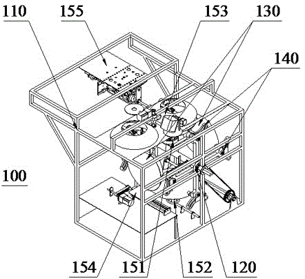
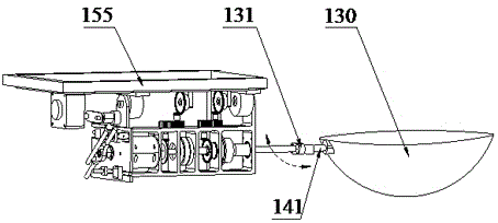
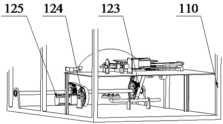
[0085] Embodiment 1: as figure 1 A continuous cooking mechanism 100 shown includes a frame 110, four pot bodies 130 for cooking, a heating mechanism 151 for heating the pot bodies 130, a cleaning mechanism 152 for cleaning the pot bodies 130, An automatic feeding mechanism 153 for automatically introducing processed food materials, an automatic discharging mechanism 154 for supporting and transporting the vegetable container, and an automatic cooking mechanism 155 for controlling the movement of the pot body 130 during the heating process. The frame 110 is a frame structure, and the above-mentioned mechanisms are arranged on the frame 110 or in the frame 110, and a heating station is formed between the heating mechanism 151 and the automatic feeding mechanism 153, and the automatic discharging mechanism 154 to form a discharging station, and a cleaning station is formed above the cleaning mechanism 152, so it also includes a pot for driving the pot body 130 to sequentially rot...
Embodiment 2
[0100] Embodiment 2: The heating mechanism, automatic cooking mechanism, automatic feeding mechanism, automatic discharging mechanism and cleaning mechanism of this embodiment are basically the same as the previous embodiment. In order to show its structure more clearly, the attached Figure 8 The above-mentioned mechanisms are omitted in the middle. In this embodiment, a pan body rotation mechanism different from that of the previous embodiment is mainly introduced. For other mechanisms, reference may be made to the previous embodiment or other embodiments below.
[0101] like Figure 8 The continuous cooking mechanism 200 shown, its pot body rotation mechanism 220 includes a power mechanism 224 and rotation brackets on both sides inside and outside, and the rotation bracket on the outside includes a ring track 221, a transmission chain 222 arranged on the ring track 221 and driving and supporting the transmission. The ratchet 223 driven by the chain 222 along the circular t...
Embodiment 3
[0105] Embodiment 3: This embodiment is based on the change of the basic structure of Embodiment 2, which is mainly reflected in the cooking limit mechanism, and its pan body rotation mechanism is basically the same as Embodiment 2, such as Figure 12 As shown, in the shown continuous cooking mechanism 300, the pot body rotation mechanism includes a power mechanism and rotation brackets on both sides inside and outside, and the rotation bracket on the outside includes a ring track 321, a transmission chain 322 arranged on the ring track 321 and driving and supporting The drive chain 322 drives the ratchet 323 along the circular track 321 . The circular track 321 is square, and four ratchets 323 are distributed at its four corners to support the transmission chain 322. The power mechanism drives one of the ratchets 323, thereby driving the transmission chain 322 to drive along the circular track 321. The structure and implementation Example 2 is basically the same.
[0106] to...
PUM
 Abstract
Description
Claims
Application Information
 - R&D
- Intellectual Property
- Life Sciences
- Materials
- Tech Scout
- Unparalleled Data Quality
- Higher Quality Content
- 60% Fewer Hallucinations
Browse by: Latest US Patents, China's latest patents, Technical Efficacy Thesaurus, Application Domain, Technology Topic, Popular Technical Reports.
© 2025 PatSnap. All rights reserved.Legal|Privacy policy|Modern Slavery Act Transparency Statement|Sitemap|About US| Contact US: help@patsnap.com


