
Network message processing method and equipment

A network message and processing method technology, applied in the field of network message processing methods and equipment, can solve problems such as unfavorable application and protocol porting, complicated methods, and reduced code versatility.

Inactive Publication Date: 2014-04-16
PHICOMM (SHANGHAI) CO LTD
View PDF3 Cites 7 Cited by
  • Summary
  • Abstract
  • Description
  • Claims
  • Application Information

AI Technical Summary

Problems solved by technology

However, this method also has certain problems: because the information after the removal of the chip manufacturer's logo is stored in the SKB structure, upper-layer applications can only obtain this part of information through some specific methods or custom function interfaces. These function interfaces require developers to define or modify the relevant network protocol stack processing parts in the kernel to be feasible, which greatly increases the difficulty of protocol porting in the future.
[0006] As mentioned above, the existing two-layer protocol development has the following main problems in the processing method of the message with the manufacturer's logo: 1) The attached manufacturer's logo changes the basic structure of the network message, causing the system network protocol stack to be unable to identify normally and cannot be used. The standard message processing method is used for sending and receiving processing, which increases the development difficulty and workload of the upper-layer application; 2) The way for the upper-layer application to obtain the underlying information provided by the manufacturer's logo is complicated, and the addition and modification of some kernel function interfaces require relatively large High technical level and experience are not conducive to the transplantation of applications and protocols between projects, resulting in a decrease in code versatility

Method used


Image

  • Network message processing method and equipment
  • Network message processing method and equipment
  • Network message processing method and equipment

Examples


Embodiment Construction

[0042] The following will clearly and completely describe the technical solutions in the embodiments of the present invention with reference to the accompanying drawings in the embodiments of the present invention. Obviously, the described embodiments are only some, not all, embodiments of the present invention. Based on the embodiments of the present invention, all other embodiments obtained by persons of ordinary skill in the art without creative efforts fall within the protection scope of the present invention.

[0043] It should be noted that, in the case of no conflict, the embodiments of the present invention and the features in the embodiments can be combined with each other.

[0044] The present invention will be further described below in conjunction with the accompanying drawings and specific embodiments, but not as a limitation of the present invention.

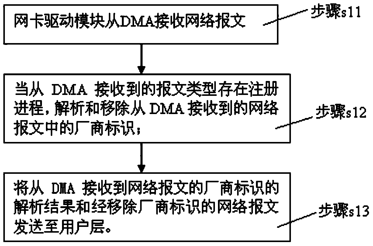
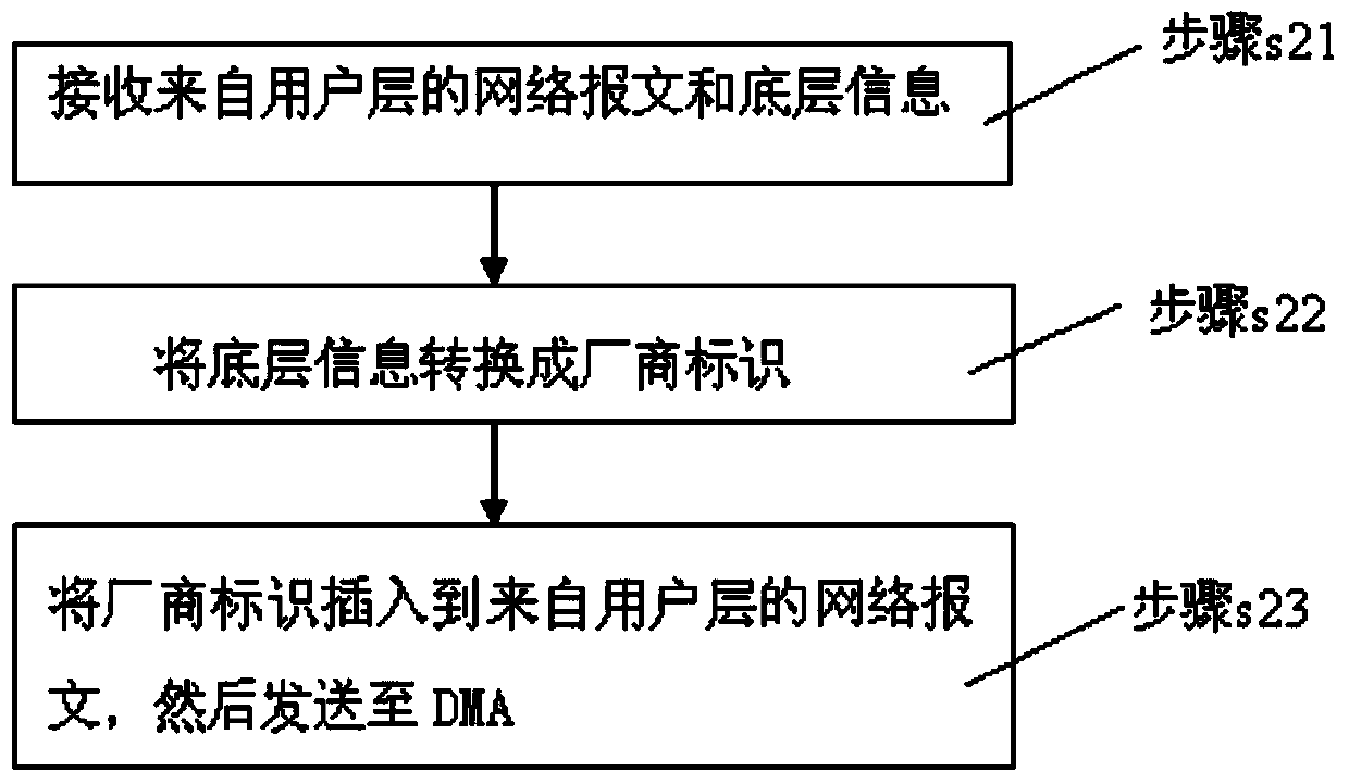
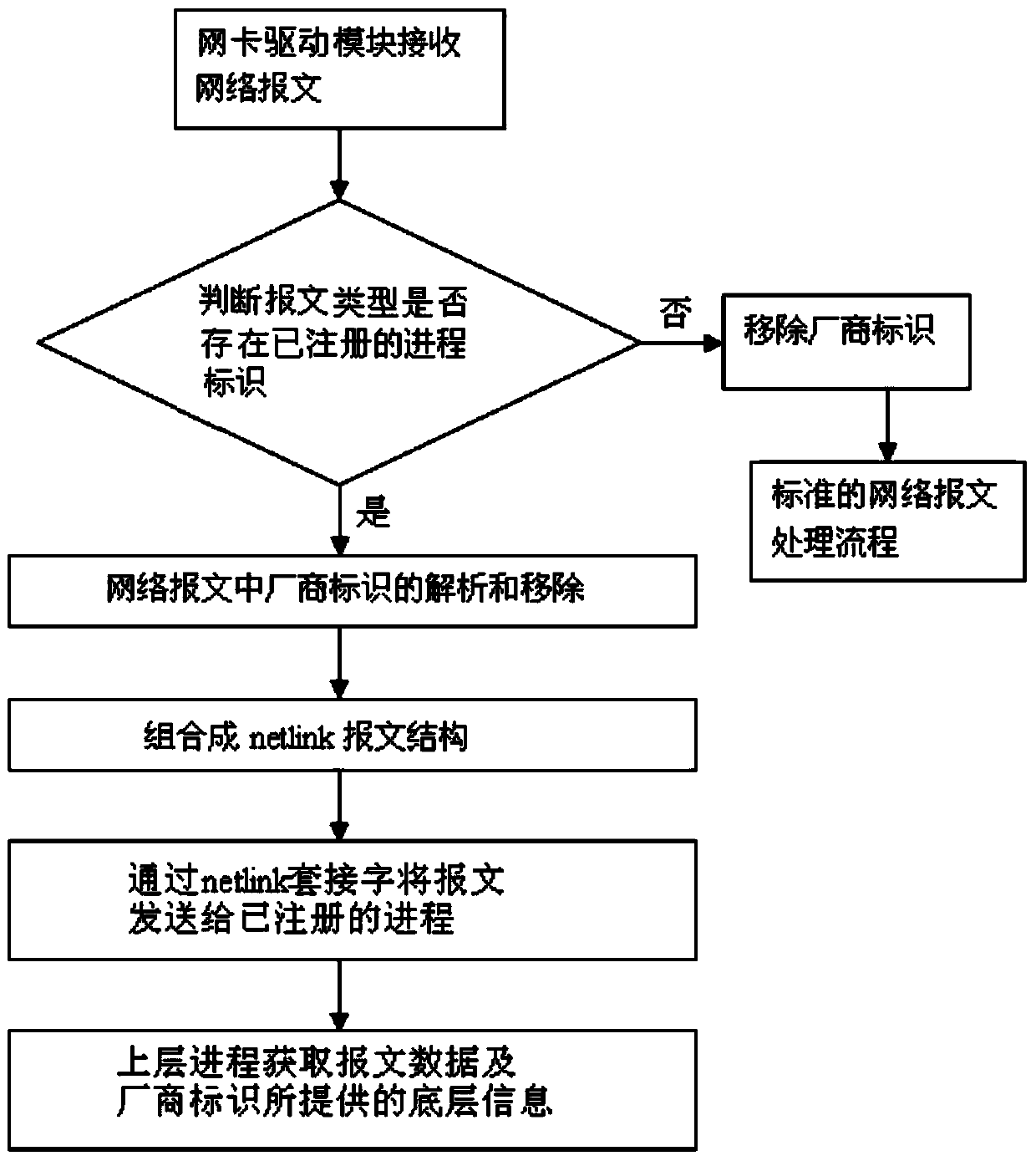
[0045] refer to figure 1 , figure 2 , image 3 , the invention discloses a network message processing method...


PUM


Abstract

The invention belongs to the technical field of network equipment, and relates to a network message processing method and equipment. The network message processing method comprises a network message receiving step and a network message transmitting step, wherein the network message receiving step comprises the steps that a network card drive module receives network messages from a DMA; if a registration progress exists in message types of the network messages, manufacturer identification in the network messages is analyzed and removed; analyzing results of the manufacturer identification of the network messages and the network messages after the manufacturer identification is removed are sent to a user layer. According to the network message processing method and equipment, a channel independent from an operating system network protocol stack is created, and no influence can be generated on three-layer software development or software development with no attention paid on bottom layer information. The network message processing method and equipment are especially suitable for the network messages with chip manufacturer identification.

Description

technical field [0001] The invention is applicable to the technical field of network equipment, and in particular relates to a network message processing method and equipment. Background technique [0002] At this stage, similar to the development process of Layer 2 or Layer 3 managed switches on the Linux platform, we often encounter a problem: for some Layer 2 network protocols, such as RSTP (rapid spanning Tree Protocol, Rapid Spanning Tree Protocol), or GVRP (Generic Attribute Registration Protocol, Generic Attribute Registration Protocol) and other developments, how the upper-layer software knows the underlying information such as the receiving port on the hardware of the protocol message; some chip manufacturers give a solution: Let the switch chip modify and send it to the CPU (Central Processing Unit, central processing unit) message structure, insert several bytes of manufacturer identification in front of the message type field to contain the underlying information...

Claims


Application Information

Patent Timeline
Patent Type & Authority Applications(China)
IPC IPC(8): H04L12/70H04L29/06
Inventor 楚嘉隆
Owner PHICOMM (SHANGHAI) CO LTD
Learn More