Mobile crushing system and mobile crushing system assembly

A crushing system, mobile technology, applied in the direction of grain processing, etc., can solve the problem of only small loading volume

Inactive Publication Date: 2014-04-16
THYSSENKRUPP IND SOLUTIONS AG
14 Cites 6 Cited by

AI-Extracted Technical Summary

Problems solved by technology

Despite the high lifting height, only small loading volumes are possible due to the arrangement of the apron conveyo...

Abstract

The invention relates to a mobile crushing system, comprising a chassis (1), a receiving bin (5a, 5b), a crusher (2), and an apron conveyor (4), which is arranged on a supporting structure (3), for conveying the material to be crushed from the receiving bin (5a, 5b) to the crusher (2), wherein the receiving bin (5a, 5b) is fastened to connection points (8) of the supporting structure (3). According to the invention, the receiving bin (5a, 5b) can be modularly exchanged. According to a first aspect, the apron conveyor (4) extends beyond a bottom of the receiving bin (5b) in a direction opposite the conveying direction (F) by means of section (9) designed to receive the material to be crushed, and the supporting structure (3) has free connection points. According to a further aspect, the receiving bin (5a, 5b) can be removed from the apron conveyor (4) along specified separation surfaces.

Application Domain

Grain treatments

Technology Topic

Electrical and Electronics engineeringCrusher +1

Image

  • Mobile crushing system and mobile crushing system assembly
  • Mobile crushing system and mobile crushing system assembly
  • Mobile crushing system and mobile crushing system assembly

Examples

  • Experimental program(1)

Example Embodiment

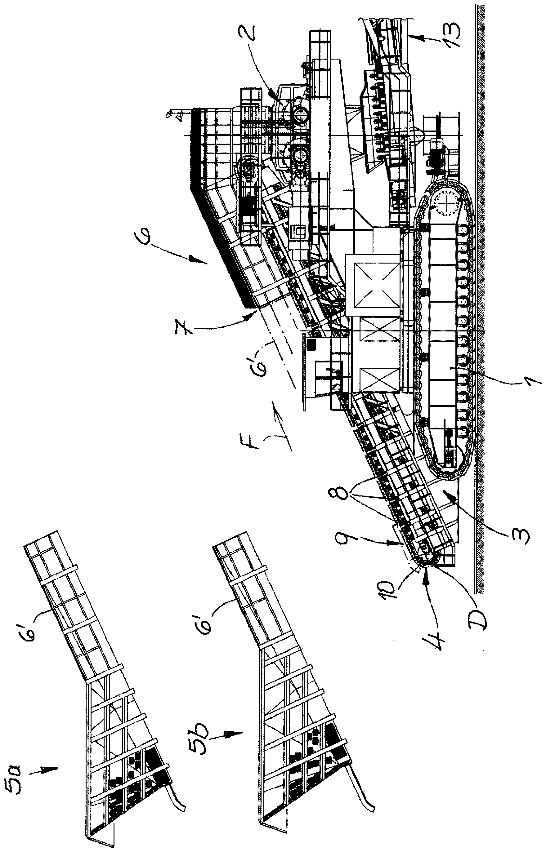
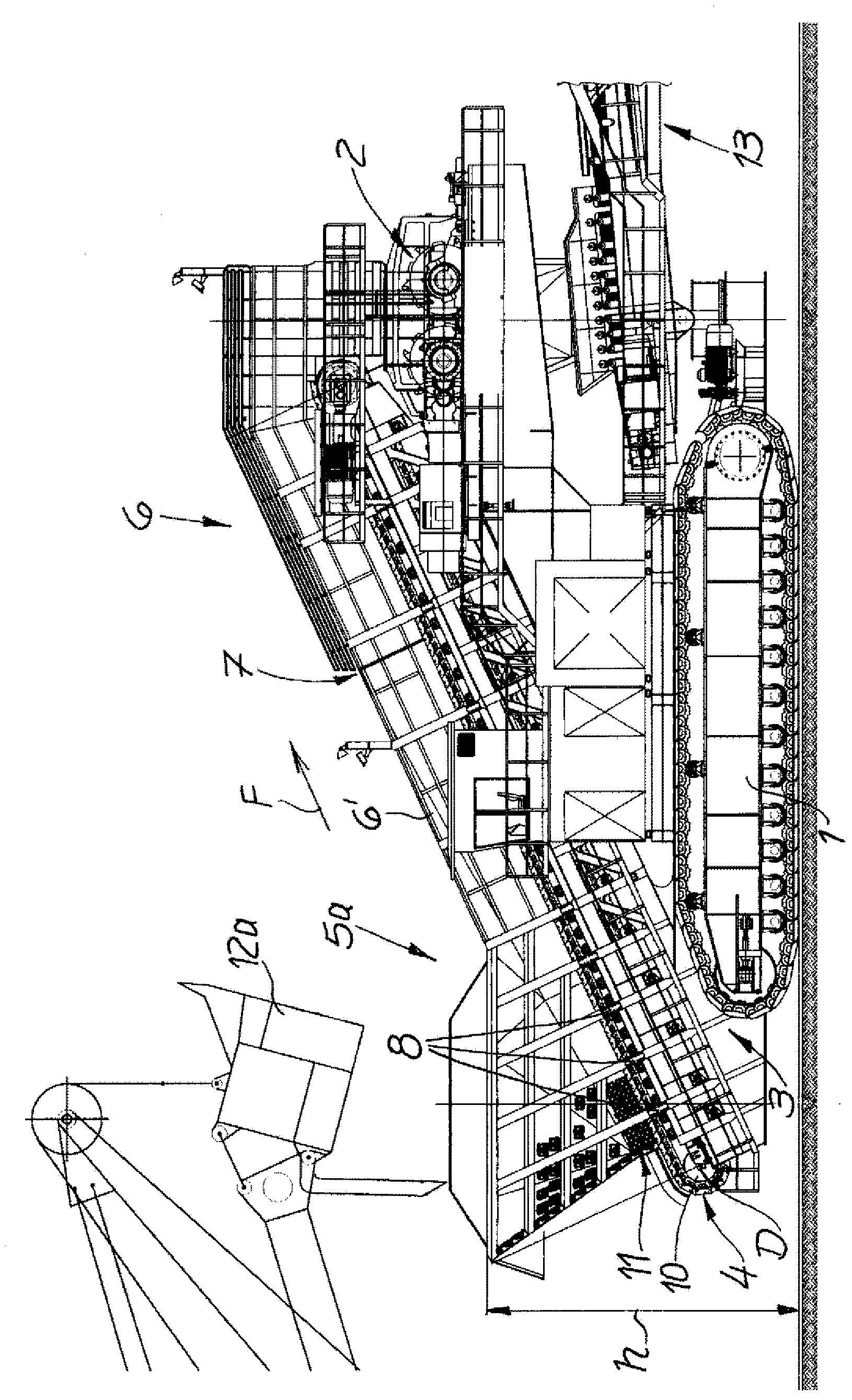
[0034] figure 1 A mobile crushing system assembly is shown, which includes a chassis 1, a crusher 2 and a plate conveyor 4 arranged on a supporting structure 3.
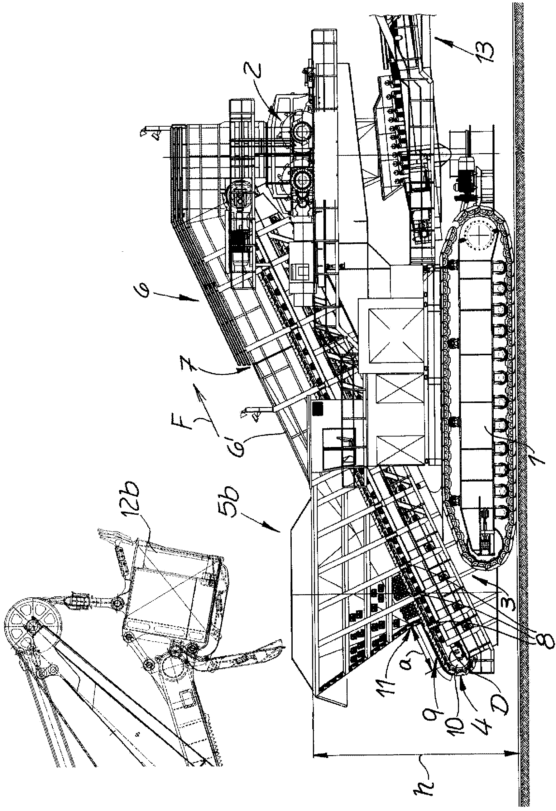
[0035] According to the present invention, the mobile crushing system assembly includes a first hopper 5a and a second hopper 5b, and the first hopper 5a and the second hopper 5b are mutually replaceable as modules. To achieve this effect, two hoppers 5a, 5b are detachably fixed to the supporting structure 3 so that the hoppers 5a, 5b can be removed from the slat conveyor 4 along a predetermined separation surface.
[0036] In the illustrated exemplary embodiment, the filling volume of the second hopper 5b is greater than the filling volume of the first hopper 5a. Since the second hopper 5b has a larger capacity, it can also be loaded by using a larger shovel 12b. During operation, the larger volume of the second hopper 5b results in a larger static load due to the inherent weight of the crushing system and the weight of the filling material conveyed therein.
[0037] However, because it is also possible to use a larger shovel 12b (see image 3 ) To load the larger second hopper 5b, so the changes related to the dynamic load are still more severe. Due to the greater total weight of each filling action and due to the higher drop height, the pulses transmitted from the second hopper 5b to the support structure 3 during the loading action are greatly increased. In order to be able to absorb the dynamic load, the second hopper 5b is arranged at a shorter distance from the crusher 2 than the distance from the first hopper 5a to the crusher 2, and therefore at a shorter distance from the center of gravity of the entire device. In the design of the mobile crushing system, lever arms that can act on both sides of the chassis 1 are considered. Due to the displacement of the second hopper 5b in the direction of the crusher 2, the crusher 2 is also arranged so as to be higher on the slat conveyor 4. Due to the higher arrangement on the slat conveyor, the drop height is also reduced, or to match the higher drop height of the larger shovel 12b. This also helps limit dynamic loads.
[0038] Therefore, in the smaller first hopper 5a, it is provided to arrange the hopper 5a away from the crusher 2, and therefore away from the center of gravity, thus extending the lever arm. So with regard to the slat conveyor 4 extending upward at an angle, the first hopper 5a is arranged lower, and therefore the loading height h (ie the height of the upper edge of the hopper 5a, which must be bridged by the shovel 12a) is significantly reduced .
[0039] According to a specific exemplary embodiment, the first hopper 5a contains 153m 3 Capacity, where the hopper 5a is designed to have 61m 3 The loading capacity of the shovel 12a. In comparison, the second hopper 5b contains 190m 3 The capacity of which the hopper 5b is designed to have 75m 3 The loading capacity of the shovel 12b. In order to make it possible to arrange the first hopper 5a and the second hopper 5b at different positions, the partition wall 6 arranged on each side of the slat conveyor 4 contains obstructions 7, wherein in each case, the partition wall 6 The lower part 6'of the is connected to the hoppers 5a, 5b and can be removed relative to the foregoing.
[0040] figure 2 A mobile crushing system with a first hopper 5a in preparation is shown, where the hopper 5a is detachably fixed to the support structure 3. The fixation can be affected by forced locking or non-forced locking of the connection. according to figure 2 , On the connection point 8 of the support structure 3, the hopper 5a is fixed by screw connection. In addition, the forced locking arrangement can provide a connected support, which can be particularly advantageous for the placement of the hoppers 5a, 5b on the support structure.
[0041] image 3 A mobile crushing system in which the first hopper 5a has been replaced by the second hopper 5b is shown. In order to compensate for higher static and dynamic loads, the second hopper 5b is arranged so as to be closer to the crusher 2 and therefore closer to the center of gravity. The lower part 6'of the partition wall 6 (the lower part 6'is fixed to the crusher 2) has a correspondingly shorter design, in which there is a slat conveyor 4 provided with a section 9 for receiving the material to be crushed in the conveying direction F Extends beyond the bottom of the hopper 5b. Therefore, according to image 3 In the configuration of, a considerable part of the slat conveyor 4 remains unused in order to make the flexible use of different hoppers 5a, 5b possible. According to the usual three-dimensional dimensions of the mobile crushing system, the distance a between the axis of rotation D of the bottom deflection roller 10 measured along the slat conveyor 4 and the rear edge 11 of the second hopper 5b is at least 1.5 m, in a specific exemplary implementation The distance mentioned in the example is 2.4m. Because the second hopper 5b is arranged so as to be displaced in the direction of the crusher 2, the second hopper 5b is freely arranged at one of the connection points 8, wherein according to figure 2 The first hopper 5a is fixed to the connection point 8.
[0042] The mobile crushing system assembly with the first hopper 5a and the second hopper 5b according to the present invention makes it possible to operate with loading equipment with different shovel sizes. according to figure 2 , Only the indicated loading equipment contains 61m 3 The filling volume of the shovel 12a. The shovel is designed in such a way that it can overcome the loading height h (which is 8.50m in the exemplary embodiment). In accordance with figure 2 In the design of, the first hopper 5a is set in such a way that the static and dynamic forces acting on both sides of the chassis 1 under the maximum load condition substantially cancel each other or at least not exceed the predetermined maximum load. Specifically, it is necessary to prevent excessive vibration due to dynamically changing forces.
[0043] according to figure 2 The arrangement with the first hopper 5a cannot be easily used with loading equipment containing a larger shovel. This is because, in the case of a larger shovel, the dynamic load will increase due to the greater mass and due to the increased drop height, and therefore there will be a risk of overloading the mobile crushing system. In addition, the volume of the first hopper 5a may be insufficient.
[0044] according to image 3 In order to use a larger shovel 12b, a second hopper 5b is provided, and the second hopper 5b matches a larger load in terms of its size and arrangement. Since the second hopper 5b is arranged so as to be closer in the direction of the crusher, it is possible to prevent overload even in the case of a larger drop weight and a larger drop height.
[0045] Therefore, in the design stage, various configurations are considered in advance, in which a balance is achieved between components arranged on both sides of the center of gravity. In the design process, it must be considered that the hoppers 5a, 5b in the mobile crushing system are arranged on one side of the center of gravity, while the crusher 2 and the discharge arm 13 (only indicated in the drawing) are arranged on the other side of the center of gravity. On one side.

PUM

no PUM

Description & Claims & Application Information

We can also present the details of the Description, Claims and Application information to help users get a comprehensive understanding of the technical details of the patent, such as background art, summary of invention, brief description of drawings, description of embodiments, and other original content. On the other hand, users can also determine the specific scope of protection of the technology through the list of claims; as well as understand the changes in the life cycle of the technology with the presentation of the patent timeline. Login to view more.
Why Eureka
Try Eureka