Method for switching in an arrangement of circuit breakers and arrangement of a plurality of circuit breakers

A technology for power switches and equipment, applied in instruments, safety arrangements, control/regulation systems, etc., and can solve problems such as automation difficulties

Inactive Publication Date: 2014-04-16
SIEMENS AG
View PDF10 Cites 0 Cited by
  • Summary
  • Abstract
  • Description
  • Claims
  • Application Information

AI Technical Summary

Problems solved by technology

Automating the execution of countermeasures is difficult, however perfo...

Method used


Image

  • Method for switching in an arrangement of circuit breakers and arrangement of a plurality of circuit breakers

Examples


Embodiment Construction

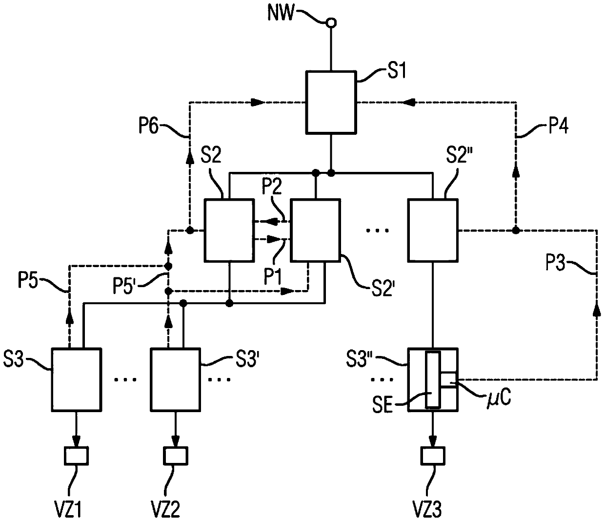
[0019] In an energy distribution installation, for example, coupled to a common current network, a plurality of power switches S1, S2, S2', S2'', S3, S3', S3'' are coupled to each other and present three levels in hierarchical form . The electrical connections are shown here by solid lines. The power switches are simultaneously coupled to each other via a data network, which is indicated by dashed lines.

[0020] Current can flow from the current network NW to the first consumer branch VZ1 via the series connection of the first-order power switch S1 , the second-order power switch S2 and the third-order power switch S3 . In the second stage, a further power switch S2' is connected in parallel to the power switch S2. Therefore, there is likewise a connection of power switches S1 , S2 ′ and S3 to consumer branch VZ1 .

[0021] The consumer branch VZ2 is coupled to the network NW via a power switch S1 of the first class, two power switches S2 and S2' connected in parallel of t...


PUM


Abstract

In order for secure switching to take place in an arrangement of a plurality of circuit breakers (S1, S2, S2', S2'', S3, S3', S3'') which are connected in series and/or parallel and are at least partially coupled to one another via a data network, a first circuit breaker (S2; S3'') capable of self-diagnosis can detect whether the desired change of its switching state has occurred, and if this is not the case, can transmit a corresponding signal (P1; P3) to a second circuit breaker (S2'; S2''), which then changes its switching state accordingly instead. The second circuit breaker (S2') is preferably connected in parallel to the first circuit breaker (S2) at power-on, and at power-down, the second circuit breaker (S2'') is preferably connected in series to the first circuit breaker (S3'').

Description

technical field [0001] The invention relates to a method for switching in an arrangement of power switches, wherein in the context of the invention such an arrangement is understood to mean that power switches are connected in series and / or in parallel with one another. A power switch should be characterized in that the actual switching unit is controlled by a data processing device, wherein the data processing device is typically designed as a microcontroller. With such a microcontroller, the power switch can handle logic tasks. In particular, a self-diagnostic function can also be provided. Background technique [0002] In a device of this type there should be a high safety effect of actually switching on the power switch that is to be switched on and actually switching off the power switch that is to be switched off. Such safe switching on and off has hitherto been implemented in energy distribution systems by superordinate systems. The system includes a plurality of m...

Claims


Application Information

Patent Timeline
IPC IPC(8): G05B9/03
CPCG05B9/03
Inventor A.博格沃特T.德里霍恩P.科帕切斯基A.克劳斯A-E.穆西奥尔G.穆勒
Owner SIEMENS AG
Why Eureka
Try Eureka