High-frequency signal transmission line and electronic equipment
一种信号线路、传输线路的技术,应用在高频匹配器、电路、印刷电路等方向
- Summary
- Abstract
- Description
- Claims
- Application Information
AI Technical Summary
Problems solved by technology
Method used
Image

Examples
Embodiment approach 1
[0039] (Structure of high frequency signal transmission line)
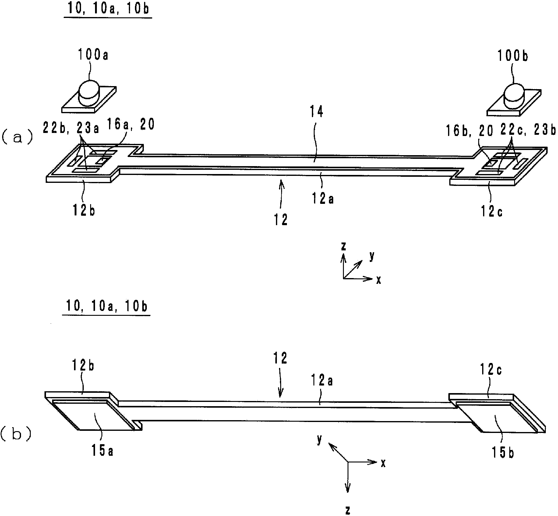
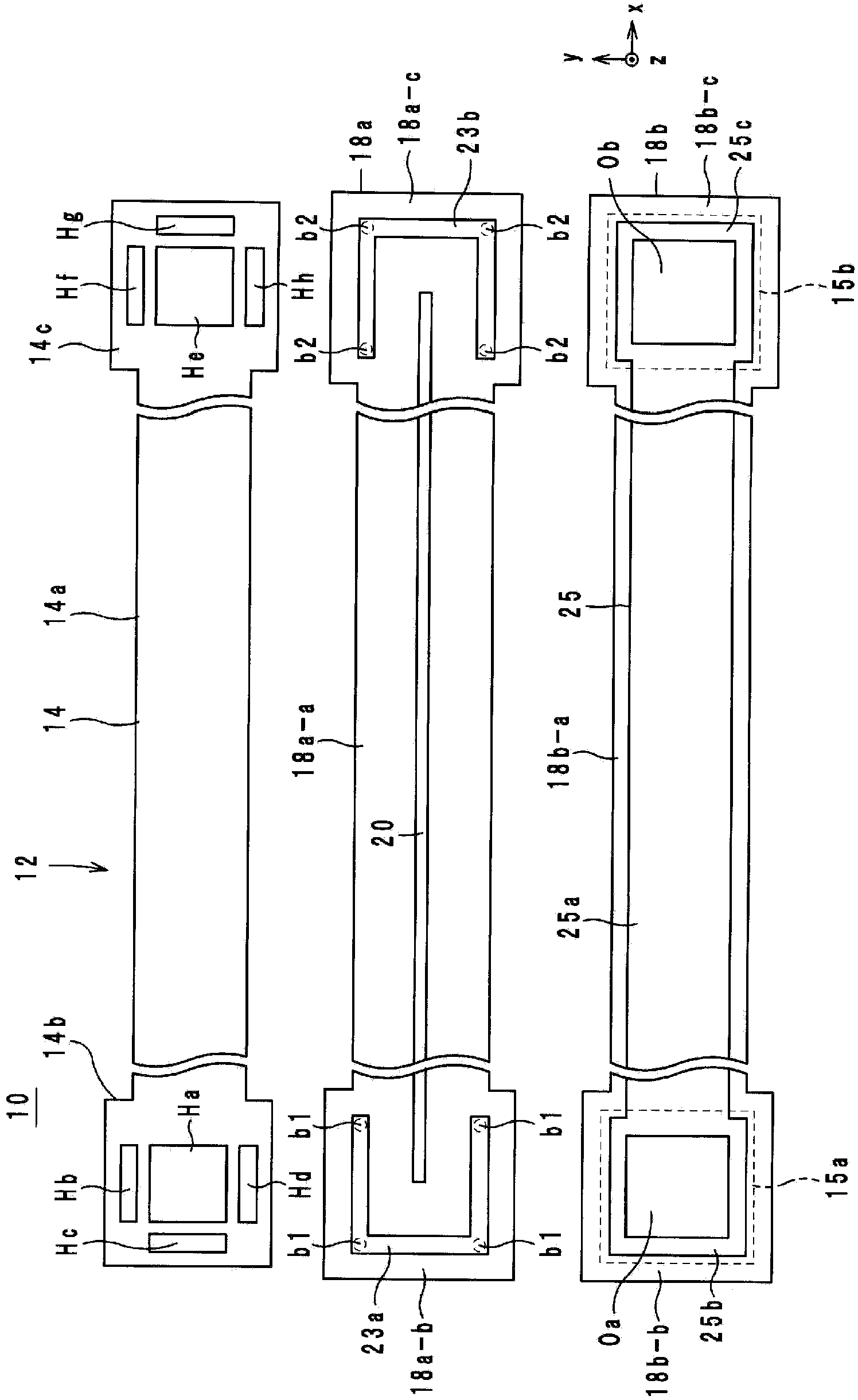
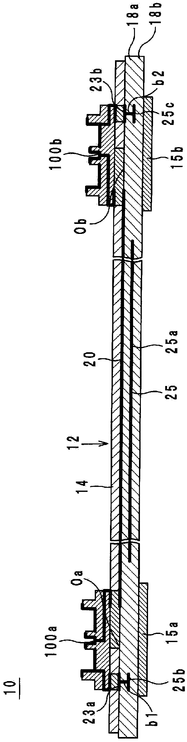
[0040] Hereinafter, the structure of the high-frequency signal transmission line according to Embodiment 1 of the present invention will be described with reference to the drawings. figure 1 It is an external perspective view of the high-frequency signal transmission line 10 according to the first embodiment. figure 2 It is an exploded view of the dielectric body 12 of the high-frequency signal transmission line 10 according to the first embodiment. image 3 It is a cross-sectional configuration diagram of the high-frequency signal transmission line 10 according to the first embodiment. Figure 4 It is an external perspective view and a cross-sectional structural view of the connector 100b of the high-frequency signal transmission line 10. in Figure 1 to Figure 4 Here, the lamination direction of the high-frequency signal transmission line 10 is defined as the z-axis direction. In addition, the longitudinal directio...
Embodiment approach 2
[0087] (Structure of high frequency signal transmission line)
[0088] Hereinafter, the structure of the high-frequency signal transmission line according to Embodiment 2 of the present invention will be described with reference to the drawings. Picture 9 It is an exploded view of the dielectric body 12 of the high-frequency signal transmission line 10a according to the second embodiment. Picture 10 It is a cross-sectional configuration diagram of a high-frequency signal transmission line 10a according to the second embodiment. Regarding the appearance perspective view of the high-frequency signal transmission line 10a, quote figure 1 .
[0089] Such as figure 1 with Picture 9 As shown, the high-frequency signal transmission line 10a includes a dielectric body 12, external terminals 16 (16a, 16b), connecting conductors 17 (17a, 17b), signal lines 20, ground conductors 22, 24, via-hole conductors b11 to b14, B1 to B6 and connectors 100a, 100b.
[0090] When viewed in plan from the...
Embodiment approach 3
[0131] (Structure of high frequency signal transmission line)
[0132] Hereinafter, the structure of a high-frequency signal transmission line according to Embodiment 3 of the present invention will be described with reference to the drawings. Picture 12 It is an exploded view of the dielectric body 12 of the high-frequency signal transmission line 10b according to the third embodiment. In addition, the external perspective view of the high-frequency signal transmission line 10b is cited figure 1 .
[0133] The main difference between the high-frequency signal transmission line 10b and the high-frequency signal transmission line 10a is that the ground conductor 24 is not provided. Hereinafter, a detailed description will be given centering on the difference.
[0134] Such as figure 1 and Picture 12 As shown, the external terminal 16a is a rectangular conductor disposed near the center of the surface of the connecting portion 18a-b. Such as figure 1 and Picture 12 As shown, the e...
PUM
 Abstract
Description
Claims
Application Information
 - Generate Ideas
- Intellectual Property
- Life Sciences
- Materials
- Tech Scout
- Unparalleled Data Quality
- Higher Quality Content
- 60% Fewer Hallucinations
Browse by: Latest US Patents, China's latest patents, Technical Efficacy Thesaurus, Application Domain, Technology Topic, Popular Technical Reports.
© 2025 PatSnap. All rights reserved.Legal|Privacy policy|Modern Slavery Act Transparency Statement|Sitemap|About US| Contact US: help@patsnap.com