
Method and device for elevator car buffer braking under unsatisfactory stagnation conditions

An elevator car and buffer braking technology, which is applied in transportation, packaging, elevators, etc., can solve the problems of increased shaft load of the traction motor, increased car self-weight, and increased car self-weight to achieve safety protection , to prevent the effect of the top rush accident

Active Publication Date: 2015-12-09
DONGNAN ELEVATOR
View PDF3 Cites 0 Cited by
  • Summary
  • Abstract
  • Description
  • Claims
  • Application Information

AI Technical Summary

Problems solved by technology

The conventional measure is to increase the weight of the car so that T 1 with T 2 Ratio T 1 / T 2 ≥e fα , to meet the stranded working condition, but this problem arises, the self-weight of the car will inevitably increase the self-weight of the counterweight, and the shaft load of the traction motor will inevitably increase. At this time, the load capacity of the traction machine must be calculated. If the calculated actual load is greater than the rated load of the motor, it is necessary to re-select and replace it with a traction machine with a greater carrying capacity, which will cause two disadvantages: (1) Waste of power and energy, or it may be the standard of a traction machine with a greater carrying capacity The product is not available, it needs to be made by non-calibration

Method used

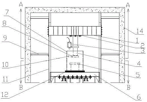
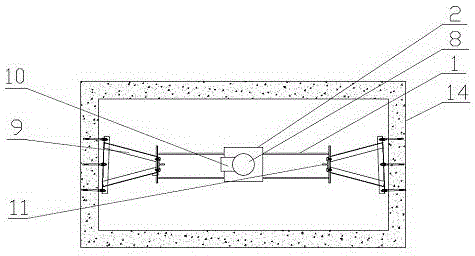
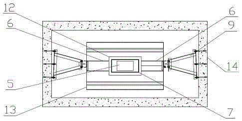

Image

  • Method and device for elevator car buffer braking under unsatisfactory stagnation conditions
  • Method and device for elevator car buffer braking under unsatisfactory stagnation conditions
  • Method and device for elevator car buffer braking under unsatisfactory stagnation conditions

Examples


Embodiment Construction

[0033] The specific embodiment of the present invention is further described below in conjunction with accompanying drawing and embodiment:

[0034] The elevator in this embodiment is driven by a traction motor. The elevator car and the counterweight are respectively suspended at both ends of the traction wire rope bypassing the traction sheave. The ratio of the pulling force on the wire rope is T 1 / T 2 , when T 1 / T 2 ≥e fα , meet the requirements of the elevator safety detention working condition, and the buffer braking method of the elevator car under the unsatisfactory detention working condition includes: the top of the elevator shaft where the elevator is running corresponds to the elevator car running to the top of the elevator shaft to set an elevator buffer and an action detection switch for detecting whether the elevator buffer is in motion; the top of the elevator car is provided with a buffer bumper, and the wiring circuit of the action detection switch is con...


PUM


Abstract

The invention relates to an elevator car buffer braking method and device not meeting a retention working condition. The method includes the steps that an elevator buffer and a motion detecting switch are arranged on the top of an elevator well, wherein the motion detecting switch is used for detecting whether the elevator buffer acts; a buffer collision plate is arranged on the top of an elevator car, a wiring loop of the motion detecting switch is connected with a main drive loop of a traction motor, when running of the elevator car does not meet the safe retention working condition, the buffer collision plate will slowly strike the elevator buffer, the upward movement of the elevator car is blocked, the elevator car is slowly stopped through braking, and an elevator is in the safe retention working condition. According to the elevator car buffer braking method and device, the danger that the elevator car of a traditional elevator continues to move upward and strikes the top of the elevator well when the traditional elevator can not meet the retention working condition of the elevator car is eliminated, the possibility that a top collision accident happens to the elevator car is avoided, and the safety of equipment and staff is protected; meanwhile, according to the technical scheme, the traction motor does not need to be replaced by a traction machine with larger load-bearing capacity, and the technical base and guarantee for further light-weight trend of the design of the elevator car are provided.

Description

technical field [0001] The invention relates to a buffer braking method for an elevator car and a device using the method. The method and the device are suitable for protection against rushing to the top when the elevator car is driven to the top of a hoistway and the stagnation working condition is not satisfied. Background technique [0002] At present, most elevators are driven by traction, that is, friction drive. The principle is: the steel wire rope goes around the traction sheave, and the elevator car and the elevator counterweight are suspended by the steel wire rope on both sides of the traction sheave. The gravity of the counterweight and the transmission of the wire rope will generate pressure on the traction sheave, thereby forming a large enough friction force. When the traction sheave rotates, the suspended steel wire rope moves up and down due to a large friction force, so that the elevator car runs up and down. When the elevator car suspended on one side goe...

Claims


Application Information

Patent Timeline
Patent Type & Authority Patents(China)
IPC IPC(8): B66B5/28B66B5/02
Inventor 蔡状秦健聪
Owner DONGNAN ELEVATOR
Learn More