
Detachable load-bearing support frame

A support frame and support rod technology, applied in the field of support frames, can solve the problems of large floor space, inconvenient use, low transportation efficiency, etc., and achieve the effects of improving transportation efficiency, reducing storage area and fast assembly speed.

Active Publication Date: 2016-09-07
CHINA CONSTR EIGHT ENG DIV CORP LTD +1
View PDF6 Cites 0 Cited by
  • Summary
  • Abstract
  • Description
  • Claims
  • Application Information

AI Technical Summary

Problems solved by technology

[0002] The existing load-bearing support frame used in the construction of large-span heavy-duty steel truss structures is mainly welded into a cubic lattice structure of 6×2.4×2.4 meters by supporting rods, strips and upper and lower bases. , a car can only transport 1 to 2 shelves at a time, the transportation efficiency is too low, and the storage area is also large, which is very inconvenient to use

Method used


Image

  • Detachable load-bearing support frame
  • Detachable load-bearing support frame
  • Detachable load-bearing support frame

Examples


Embodiment Construction

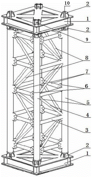
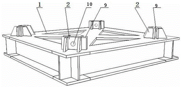
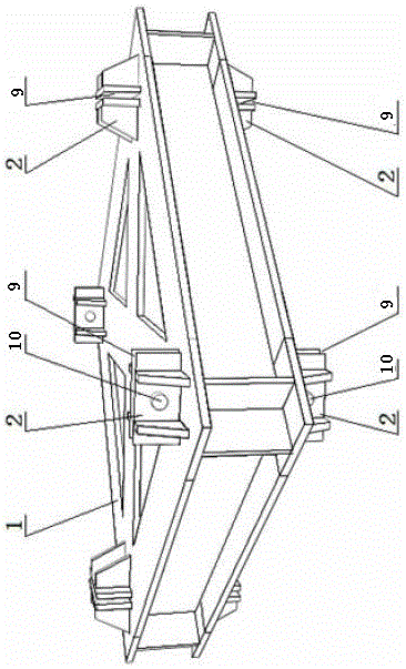
[0013] See attached Figure 1-5 , the number 1 in the figure is a square base, 2 is a support base, 3 is a fixed cross bar, 4 is a fixed slant bar, 5 is a support bar, 6 is a connecting plate, 7 is a movable cross bar, 8 is a movable slant bar, and 9 is Mounting groove, 10 and 11 are latch holes, 12 is a mounting plate, and 13 is a support rod connector.

[0014] The accompanying drawings disclose a non-restrictive structural diagram of an embodiment of the present invention, which is further described in conjunction with the accompanying drawings as follows:

[0015] The detachable load-bearing support frame of the present invention, such as figure 1 As shown, its structure includes a square base 1, a support plate, a movable cross bar 7 and a movable diagonal bar 8, wherein the support plate is composed of two support bars 5 and fixed cross bars 3 and fixed inclined bars distributed between the support bars. The rod 4 is welded, and the support rod 5 is welded with a conne...


PUM


Abstract

The invention discloses a portable load-bearing support frame. The portable load-bearing support frame comprises a square base, support plates, movable transverse rods and movable diagonal rods, wherein each support plate is formed by welding two support rods and fixed transverse rods and fixed diagonal rods distributed between the support rods; connecting plates provided with pin holes are welded on the support rods; brace rod seats provided with mounting grooves and pin holes are welded on the four top corners on one side or both sides of the square base; mounting plates provided with pin holes are welded at the two ends of each support rod respectively; the two support plates are arranged on the four brace rod seats of the square base; the movable transverse rods and the movable diagonal rods are arranged on the connecting plates between two corresponding support rods through pins or bolts. The huge-size load-bearing support frame fixedly into a whole is transported or stored by being disassembled into parts, thereby greatly increasing the transport efficiency and reducing the storage area. The portable load-bearing support frame has the advantages of high field assembly field, flexibility in adjusting the mounting height as required, and the like, and is a load-bearing support frame which is more consistent with the construction requirement.

Description

technical field [0001] The invention relates to a support frame, in particular to a load-bearing support frame used for engineering construction of a large-span heavy-duty steel truss structure. Background technique [0002] The existing load-bearing support frame used in the construction of large-span heavy-duty steel truss structures is mainly welded into a cubic lattice structure of 6×2.4×2.4 meters by supporting rods, strips and upper and lower bases. , a car can only transport 1 to 2 shelves at a time, the transportation efficiency is too low, and the storage area is also large, which is very inconvenient to use. Contents of the invention [0003] The purpose of the present invention is to overcome the shortcomings of the above-mentioned existing load-bearing support frame, and to design a portable load-bearing support frame that is convenient for transportation, storage and installation. [0004] The detachable load-bearing support frame of the present invention has...

Claims


Application Information

Patent Timeline
Patent Type & Authority Patents(China)
IPC IPC(8): E04G25/02
Inventor 周克董继勇朱雪亮吴聚龙董巍巍余雷
Owner CHINA CONSTR EIGHT ENG DIV CORP LTD
Learn More