Tooth clamp type connector

A connector and card-type technology, applied in the direction of belts/chains/gears, transmission elements or pulleys, ropes or cables, textile cables, etc., can solve operational obstacles, inconvenient real-time adjustments, and difficult to accurately grasp the penetration length of steel wires And other issues

Active Publication Date: 2014-04-23
宁波迅联机械制造有限公司
View PDF6 Cites 3 Cited by
  • Summary
  • Abstract
  • Description
  • Claims
  • Application Information

AI Technical Summary

Problems solved by technology

[0005] However, it can be known from the above two patents that neither of the above two patents can solve the problem of re-drawing from the penetration end when the steel wire is inserted into the connector for too long. It is fixed after being penetrated into the connector structure, and cannot be withdrawn from the hole for accommodating the steel wire. When connecting the steel wire, it is often difficult to accurately grasp the penetration length of the steel wire, and it needs to be adjusted continuously to penetrate the steel wire into a suitable length, and those skilled in the art have never considered the method of withdrawing steel wire to solve this problem, and directly adopt the method of cutting excess length steel wire to solve this problem, which will cause serious waste of metal resources in a large number of uses, and at the same time It is also inconvenient to adjust in real time, which hinders the operation

Method used


Image

  • Tooth clamp type connector
  • Tooth clamp type connector
  • Tooth clamp type connector

Examples


Embodiment 1

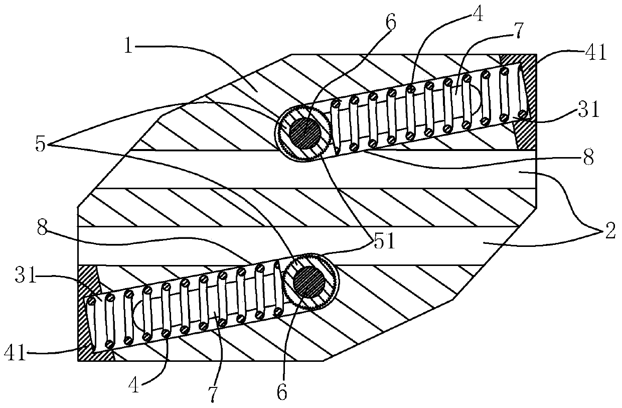
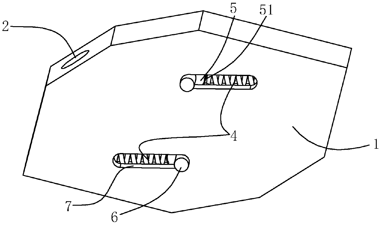
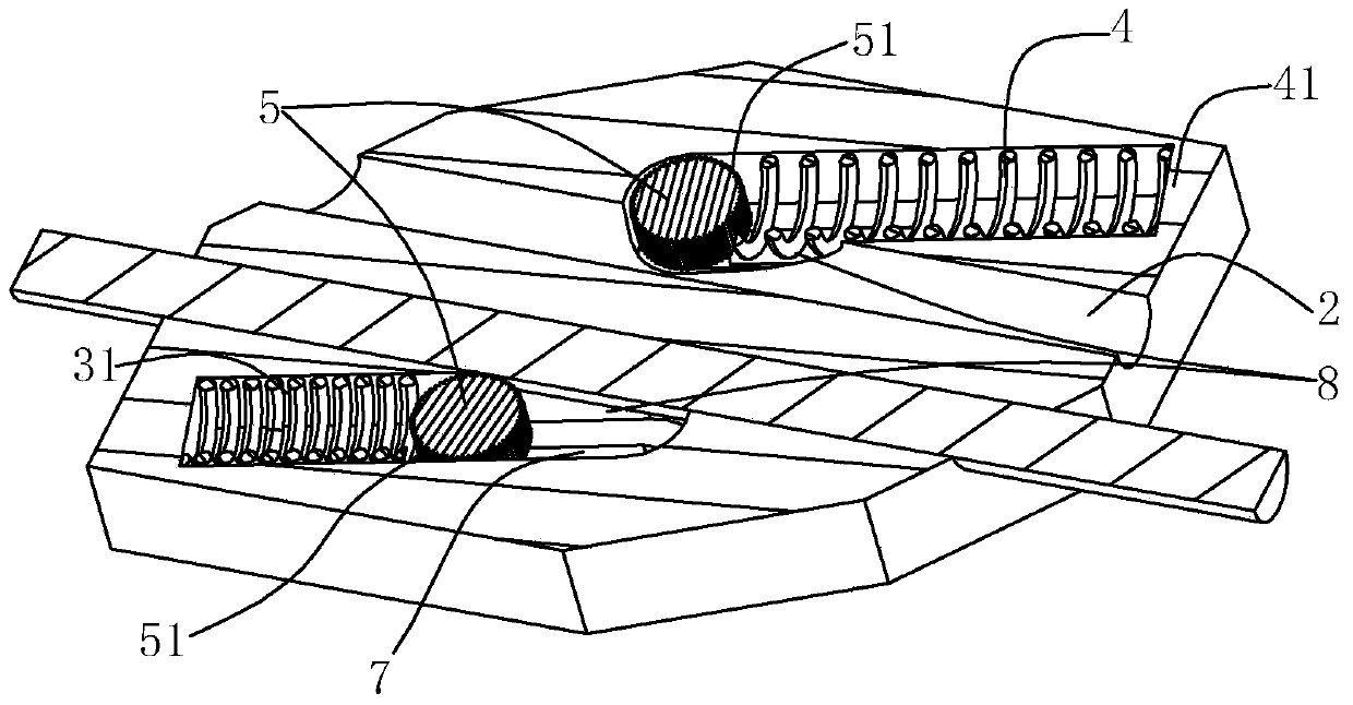
[0030] like figure 1 , figure 2 and image 3 As shown, the card connector in this embodiment includes

[0031] A card connector, comprising a housing 1, the housing 1 has a threading hole 2 and a bar hole 31;

[0032] The locking gear 5 is arranged in the bar hole 31, and the periphery of the locking gear 5 has locking teeth 51;

[0033] The elastic member 4 is arranged in the bar hole 31;

[0034] The strip hole 31 is arranged along the movement direction of the elastic member 4, the axis of the strip hole 31 intersects with the axis of the threading hole 2 to form a lock angle of α, and the angle of the lock angle α is 15°. The part where the hole 31 intersects with the threading hole 2 forms a local communication area 8, and the elastic member 4 acts on the locking gear 5 to drive the locking gear to move in the bar hole 31, so that part of the locking gear 5 is locked. 51 can enter and exit the local communication area 8, so as to realize the locking and release of t...

Embodiment 2

[0045] like Figure 4 As shown, the difference from the first embodiment is that there is an accommodating cavity 3 inside the casing, the threading hole 2 has a partly communicating area 8 with the accommodating cavity 3 , and the locking gear 5' is arranged in the accommodating cavity 3 , the peripheral portion of the locking gear 5' has locking teeth 51', and the rest is smooth, and the locking teeth 51' can enter and exit the local communication area 8;

[0046] In addition to being provided with an elastic member 4, the accommodating chamber 3 is also provided with a fixed rod 32, the first end of the elastic member 4 is fixedly arranged on the inner end surface of the accommodating chamber 3 near the exit end of the threading hole 2, and the elastic The second end of the piece 4 abuts against the locking gear 5' or is connected to the locking gear 5', and the first end of the fixing rod 32 is fixedly arranged on the inner end surface of the accommodating cavity 3 near th...

Embodiment 3

[0055] like Figure 5 and Image 6 As shown, the difference between the present embodiment and the first embodiment is that the tooth card connector also includes two push buttons 61, which are located outside the housing 1 and are respectively connected to the lever 6 of the card gear 5. end connected. Not only is it convenient to push the lever, but it also increases the comfort of fingers holding the lever,

[0056] In order to achieve a beautiful appearance and to facilitate production, the push button 61 is integrated outside the housing 1 in the shape of a sliding sleeve, straddling the housing 1, and is pushed when the user recognizes and releases the connecting line. Pushing direction of button (61), can also be provided with pushing direction mark protrusion on described sliding sleeve shape push button 61, or directly paste the pushing direction icon of sliding sleeve shape push button 61 on described sliding sleeve shape push button 61.

[0057] For the convenien...


PUM


Abstract

The invention relates to a tooth clamp type connector. The tooth clamp type connector comprises a shell, wherein a threading hole and an accommodating cavity are formed in the shell and are locally communicated with each other; a clamping gear and an elastic piece are arranged in the accommodating cavity; the peripheral edge of the clamping gear is locally provided with clamping teeth at least; the elastic piece acts on the clamping gear, so that the clamping teeth of the clamping gear tend to a local communicated area of the threading hole and the accommodating cavity; outwards raised shifting rods are arranged on two side surfaces, which are perpendicular to the moving direction, of the clamping gear; long and narrow holes which are formed along the moving direction of the clamping gear are formed in the corresponding portions of the side wall of the accommodating cavity; and two ends of each shifting rod of the clamping gear are exposed out of the corresponding long and narrow hole. The tooth clamp type connector has a function of locking a connecting line, the clamping gear can be driven to press a spring by using the shifting rod, so that movable space is reserved for the penetrated connecting line, and the purpose of adjusting the penetration length of the connecting line or withdrawing the connecting line is achieved.

Description

technical field [0001] The invention relates to a connector used for connecting wires, in particular to a tooth clip connector with a release function. Background technique [0002] Connector is a common tool used to connect leads in production and life. In the field, countryside, battlefield, factory, warehouse and other places where metal fences are reinforced or wire mesh is erected, a quick connection is often used. For the tooth clip connectors with obliquely pulled tension lines, the existing tooth clip connectors can effectively meet the connection requirements in use. [0003] The authorized announcement number is CN2683934Y (application number is 200320122503.3) Chinese utility model patent "tooth clip type steel wire connector", which discloses a tooth clip type steel wire connector including a connecting sleeve, a spring arranged in the connecting sleeve, a connecting sleeve Two threading holes with approximately the same diameter and parallel to each other are a...

Claims


Application Information

Patent Timeline
Patent Type & Authority Applications(China)
IPC IPC(8): F16G11/00
Inventor 吴文杰
Owner 宁波迅联机械制造有限公司
Why Eureka
Try Eureka