
LED (light emitting diode) ceiling lamp in multiple-light-distributing mode and multiple-light-distributing method for LED ceiling lamp

A technology of LED ceiling lamps and modes, which is applied in the direction of semiconductor devices, light sources, electric light sources, etc. of light-emitting elements, to achieve the effects of simple installation, small installation space and low cost

Active Publication Date: 2014-04-23
SUZHOU HONG YIFENG PHOTOELECTRIC
View PDF5 Cites 13 Cited by
  • Summary
  • Abstract
  • Description
  • Claims
  • Application Information

AI Technical Summary

Problems solved by technology

At present, LED ceiling lamps are mostly used in indoor homes. In order to realize the creation of the entire space light environment, customers usually need to import a variety of lamps to achieve this. In terms of cost, installation and application convenience, this solution is not the best choice.

Method used


Image

  • LED (light emitting diode) ceiling lamp in multiple-light-distributing mode and multiple-light-distributing method for LED ceiling lamp
  • LED (light emitting diode) ceiling lamp in multiple-light-distributing mode and multiple-light-distributing method for LED ceiling lamp
  • LED (light emitting diode) ceiling lamp in multiple-light-distributing mode and multiple-light-distributing method for LED ceiling lamp

Examples


Embodiment 1

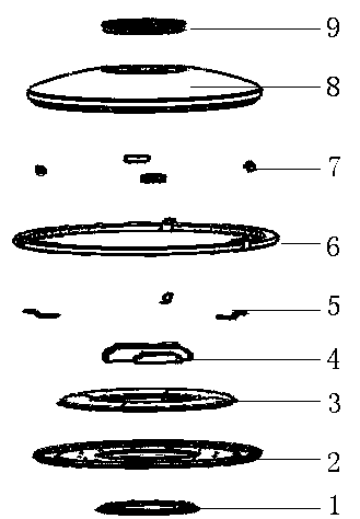
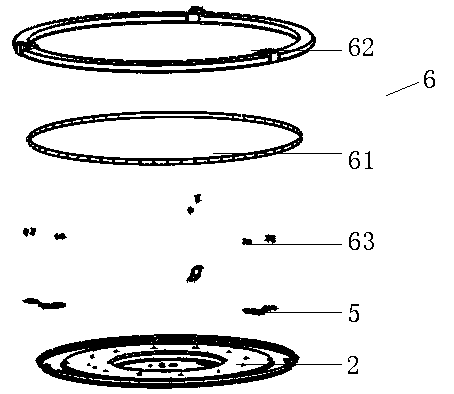
[0041] like figure 1 As shown, the LED ceiling lamp with multiple light distribution modes mainly includes a lamp panel 2, a direct light illumination module 3 arranged on the lamp panel 2, and a direct light illumination module 3 arranged on the lamp panel 2 and located in the ring. The driver and controller module 4 , the indirect light illumination module 6 arranged on the side of the lamp panel 2 , and the lampshade 8 snapped on the lamp panel 2 through the lampshade buckle 7 . An accent lighting module 9 can also be arranged on the lampshade 8 . The lamp panel 2 is connected to the installation base 1, and the ceiling lamp is fixedly connected to the ceiling through the installation base 1.

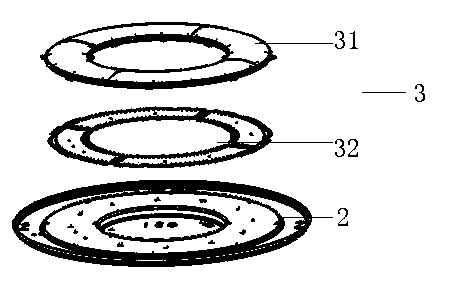
[0042] combine figure 2 As shown, the direct light illumination module 3 includes a direct light LED substrate 32 connected to the lamp panel 2 and a direct light transparent member 31 covered on the direct light LED substrate 32 . The direct-light LED substrate 32 and the direc...

Embodiment 2

[0056] like Figure 5 As shown, another structural form of indirect light lighting module 6a can be used in this embodiment, and the indirect light lighting module 6a includes a plurality of LED lighting modules 6a1 ringed on the side of the lamp panel 2 and a plurality of indirect light light-transmitting part 6a2 , the LED light emitting module 6a1 is covered by the indirect light translucent part 6a2 and snapped onto the lamp panel 2 . The LED light-emitting module 6a1 is matched with the indirect light-transmitting member 6a2. In this embodiment, five LED lighting modules 6a1 and an indirect light-transmitting member 6a2 are used. Each LED lighting module 6a1 may include one or more LED lamps. Preferably, the LED lamps in the LED lighting module 6a1 adopt LED lamps with multiple color temperatures arranged alternately. The indirect light translucent member 6a2 is atomized to make the irradiated light softer.

[0057] Preferably, a plurality of cavities 2a for accommoda...

Embodiment 3

[0060] like Image 6 As shown, another structural form of the accent lighting module 9a can be used in this embodiment. The accent lighting module 9a is a luminous body with a light distribution curve of small and medium angles, including a plurality of LED light emitting modules 9a2 and a cover mounted on the decorative ring 9a1. The optical lens 9a3 on the LED lighting module 9a2. The decorative ring 9a1 is connected to the lamp panel 2 through the bracket piece 9a4, and a plurality of LED light-emitting modules 9a2 are arranged around the decorative ring 9a1, and the lampshade is covered on the outside of the decorative ring 9a1, and the light emitted by the LED light-emitting modules 9a2 is mainly directed towards the lampshade. Focused areas in the space are illuminated.

[0061] When installing the accent lighting module 9a in this embodiment, first assemble the LED light emitting module 9a2, then embed the LED light emitting module 9a2 into the interior of the decorati...


PUM


Abstract

The invention discloses an LED (light emitting diode) ceiling lamp in a multiple-light-distributing mode and a multiple-light-distributing method for the LED ceiling lamp. The LED ceiling lamp in the multiple-light-distributing mode comprises a lamp panel, a direct lighting module, a lampshade and at least one indirect lighting module or accent lighting module, wherein the lampshade is clamped on the lamp panel; the direct lighting module is an LED illuminator with a medium-angle light-distributing curve; the indirect lighting modules or the accent lighting modules emit light together with the direct lighting module; the indirect lighting modules are LED illuminators with wide-angle light-distributing curves and are annularly distributed on a side surface of the lamp panel, and emit light towards surrounding space by using the wide-angle light-distributing curves; the accent lighting modules are LED illuminators with medium-and-small-angle light-distributing curves, and illuminate a key area in space facing the lampshade by using the medium-and-small light-distributing curves; and light emitting of the lighting modules is controlled by a driver and a controller module. Multi-mode light distribution of the LED ceiling lamp can be realized; the brightness and the color temperature can be regulated; and the LED ceiling lamp is mounted easily, conveniently and quickly, and occupies small space.

Description

[0001] technical field [0002] The invention relates to an LED ceiling lamp, which belongs to the technical field of lighting applications. Background technique [0003] Traditional ceiling lamps generally use ring-shaped fluorescent lamps as light sources, and the lights are all irradiated downwards. At present, because LED has the advantages of long life, high luminous efficiency, energy saving and environmental protection, etc., it is imperative for LED to replace traditional fluorescent lamps as the ceiling lamp as the light source. However, the LED ceiling lamps currently on the market generally have a single light distribution form, and all use lamps to illuminate downwards. They are simply ceiling lamps that simply replace traditional circular fluorescent lamps as light sources. [0004] With the development of the economy, lighting design has not only focused on brightness at the beginning, but now it is not only pursuing brightness, but also pursuing light quality...

Claims


Application Information

Patent Timeline
IPC IPC(8): F21S8/04F21V19/00F21V5/04F21V5/00F21V23/00F21Y101/02F21Y115/10
Inventor 孙清波
Owner SUZHOU HONG YIFENG PHOTOELECTRIC
Learn More