A Replaceable Installation Method of Embedded Vibrating Wire Strain Gauge

An installation method and a technology of strain gauges, which are applied in the direction of measuring devices and instruments, can solve the problems of no embedded vibrating wire strain gauges, etc., and achieve the effect of convenient, reliable and low-cost replacement of strain gauges and wires

Active Publication Date: 2016-03-23
NORTH CHINA UNIV OF WATER RESOURCES & ELECTRIC POWER
View PDF4 Cites 0 Cited by
  • Summary
  • Abstract
  • Description
  • Claims
  • Application Information

AI Technical Summary

Problems solved by technology

And the embedded vibration type strain gauge has a certain survival rate after installation, so there is a problem of replacing the vibrating wire strain gauge in the process of structural monitoring
At present, there are many types of vibrating wire strain gauges, but no replaceable embedded vibrating wire strain gauges have been found.

Method used


Image

  • A Replaceable Installation Method of Embedded Vibrating Wire Strain Gauge
  • A Replaceable Installation Method of Embedded Vibrating Wire Strain Gauge
  • A Replaceable Installation Method of Embedded Vibrating Wire Strain Gauge

Examples


Embodiment Construction

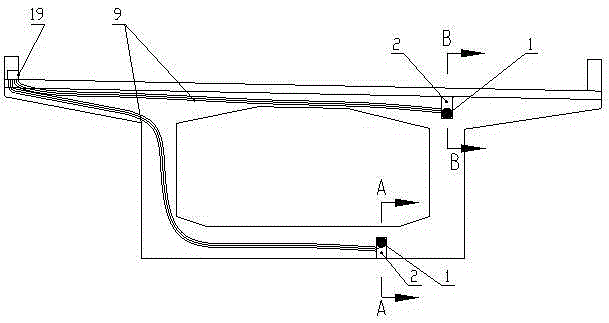
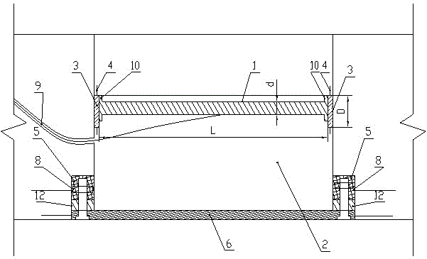
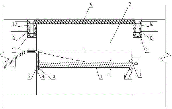
[0036] Such as figure 1 As shown, the installation method of the present invention is aimed at the vibrating wire strain gauge, and the vibrating wire strain gauge can be used to measure the stress change of the top plate, bottom plate and web of the beam. Its shape is dumbbell-shaped, and its structure is a cylinder in the middle, and the two ends of the cylinder are integrally connected with metal discs 10. The diameter of the metal disc 10 is D, and the diameter D of the metal disc 10 is greater than the diameter d of the cylinder.

[0037] The specific installation steps are:

[0038] 1. First select the model of the vibrating wire strain gauge, determine the length L of the strain gauge, and the diameter D of the metal disc 10 at both ends;

[0039] 2. Determine the point where the strain is to be measured, determine the position of the top or bottom plate, and measure the distance H between the vibrating wire strain gauge and the outer surface of the concrete;

[0040]...


PUM


Abstract

The invention relates to a replaceable embedded vibrating-string strain gauge installation method. A vibrating-string strain gauge can be used for measuring the strain variation of a top plate, a soleplate and a web of a beam; the vibrating-string strain gauge is in a dumbbell shape, the middle part of the vibrating-string strain gauge is in a cylindrical shape, two ends of the cylindrical middle part are respectively and integrally connected with a metal wafer, the diameter of each metal wafer is D, and the diameter D of each metal wafer is greater than the diameter d of the cylinder. A working mechanism for realizing the replaceable embedded vibrating-string strain gauge is as follows: when the strain gauge loses effectiveness, a sealing cover plate is opened, solvent of epoxy resin binder is injected to two ends of the strain gauge, after the strain gauge is immersed for a period of time, the binder between a stainless steel plate and a steel plate on each end of the strain gauge is dissolved, and the strain gauge is taken out; a novel strain gauge is connected with a conducting wire, and after the solvent is completely volatized, the steel plates on two ends of the strain gauge are coated with epoxy resin, and the strain gauge stretches into reserved holes.

Description

technical field [0001] The invention relates to a sensor installation in the technical field of civil engineering, in particular to a method for installing a vibrating wire strain sensor. Background technique [0002] The vibrating wire strain gauge has the advantages of simple structure, reliable operation, standard frequency signal output signal, and no need to be powered on all the time. It has been widely used in key parts of reinforced concrete structures such as large bridges, dams, tunnels, and important buildings. Condition monitoring. However, according to literature reports, the service life of the vibrating wire strain gauge in the experimental environment can reach about 25 years. Because the application time of the vibrating wire strain gauge in engineering is relatively short, its service life is still unknown in practice. The service life of reinforced concrete structures can generally reach decades or even hundreds of years. Moreover, the embedded vibration...

Claims


Application Information

Patent Timeline
Patent Type & Authority Patents(China)
IPC IPC(8): G01B21/32
Inventor 陈记豪
Owner NORTH CHINA UNIV OF WATER RESOURCES & ELECTRIC POWER
Why Eureka
Try Eureka