Supercharge Your Innovation With Domain-Expert AI Agents!

Tire information acquisition apparatus, tire state monitoring system, and method of collecting puncture repairing fluid

A technology for obtaining devices and repair fluids, which is applied in tire measurement, tire inflation valves, tire parts, etc., can solve problems such as the inability to recycle flat tire repair fluids, and achieve the effect of easy recycling

Active Publication Date: 2014-04-23
THE YOKOHAMA RUBBER CO LTD
View PDF6 Cites 0 Cited by
  • Summary
  • Abstract
  • Description
  • Claims
  • Application Information

AI Technical Summary

Problems solved by technology

[0011] However, the acquisition device of Patent Document 1 has an L-shaped air valve, so it is difficult to insert the tube into the tire cavity area via the air valve
So, it may not be possible to recycle the puncture repair fluid
[0012] In addition, the acquisition device of Patent Document 1 is provided with a sensor unit for sensing the air pressure in the tire cavity area in an exposed manner near the air passage opening formed on the surface of the TPMS valve facing the tire cavity area, so the tire blowout repair fluid When injected into the tire cavity area, puncture repair fluid may adhere to the sensor unit

Method used


Image

  • Tire information acquisition apparatus, tire state monitoring system, and method of collecting puncture repairing fluid
  • Tire information acquisition apparatus, tire state monitoring system, and method of collecting puncture repairing fluid
  • Tire information acquisition apparatus, tire state monitoring system, and method of collecting puncture repairing fluid

Examples


Deformed example 1

[0111] Refer below Figure 12 and Figure 13 , right with Figure 5 An example (Modification 1) of the through hole 130 in which the shown through hole 130 is different will be described.

[0112] Such as Figure 12 and Figure 13As shown, the cross-sectional area of ​​the through hole 130 of the tire valve 104 can be increased from the case side opening 130a to the outside opening 130b, and a hole protruding from the inner wall surface and extending along the through hole is provided on the inner wall of the through hole 130 . 130 steps extending in the connecting direction. In this case, the height H of the step is preferably 1 mm or less. In addition, if Figure 12 As shown, when the step is formed in such a manner that the hole cross-sectional area of ​​the through hole 130 of the tire valve 104 becomes gradually larger from the case side opening 130a to the outer opening 130b, the pipe 20 inserted into the through hole 130 can be inserted along the surface of the st...

Deformed example 2)

[0115] Figure 14 (a), (b) are pairs and Figure 5 An example (Modification 2) of the communicating hole 126 different from the illustrated communicating hole 126 is illustrated. Figure 14 (a), the cross-sectional shape of the communicating hole 126 shown in (b) and Figure 5 The illustrated cross-sectional shape of the communication hole 126 is different.

[0116] Such as Figure 14 As shown in (a) and (b), the extending direction of the communication hole 126 at the cavity region side opening 126a of the communication hole 126 ( Figure 14 (a), (b) E2 direction) can be formed so that it may be directed outward in the tire radial direction. At this time, the tube 20 inserted into the tire valve 104 is guided to extend outward in the tire radial direction from the cavity region side opening 126 a via the through hole 130 and the communication hole 126 . As a result, the tube 20 can be easily inserted outside the tire cavity region in the tire radial direction, so that th...

Deformed example 3)

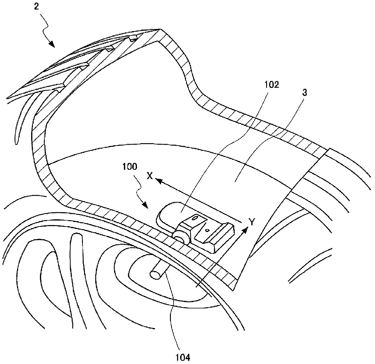
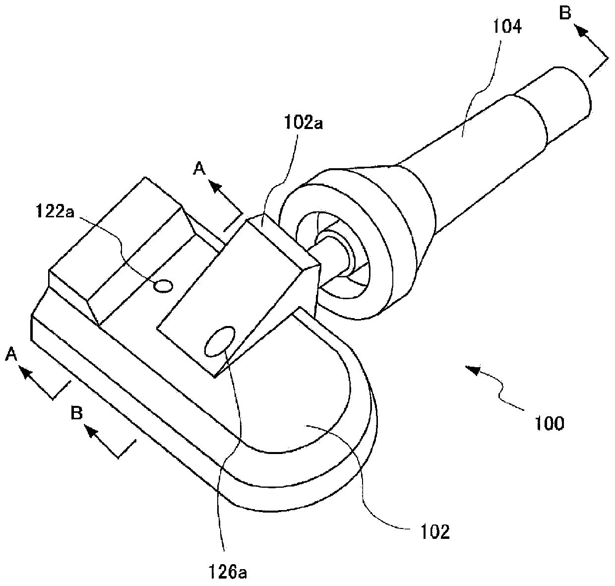
[0120] Figures 15-17 It is a figure explaining another example (modification 3) of the acquisition device 100 different from the above-mentioned embodiment. Figures 15-17 The acquisition device 100 shown is different from the acquisition device 100 of the above-mentioned embodiment in that a detachable mechanism for detachably holding the through portion 128 of the tire valve 104 inserted into the communication hole 126 is provided on the case 102 .

[0121] By making the space between the case 102 and the tire valve 104 detachable, for example, even if the tire valve 104 is adhered to the tire valve 104 by the puncture repair fluid 4 during puncture repair, only the tire valve 104 can be removed and replaced with a new tire valve.

[0122] Figure 15 It is a figure explaining an example of the modification 3. exist Figure 15 The shown penetration portion 128 has a male thread formed on the outer peripheral surface, and a female thread is formed on the inner wall of the ...


PUM


Abstract

An acquisition apparatus disposed in a tire hollow area for acquiring tire information regarding a tire state includes: a sensor that detects the state of gas in the tire hollow area as the tire information; a valve; and a casing with an internal space for storing the sensor in a compartmentalized state with respect to the tire hollow area, a vent hole for providing communication between the internal space and the tire hollow area, and a communication hole connected to a hollow area side opening portion of the valve at an end closer to the tire hollow area and providing communication between the hollow area side opening portion and the tire hollow area. The diameter of the communication hole and the inner diameter of the valve have a minimum value of not less than 2.5 mm, and the vent hole is disposed at a position outside a range of less than 140 DEG of the angle of view from a central position corresponding to the position of the opening of the communication hole with respect to a central direction aligned with the direction of extension of the communication hole from the opening of the communication hole at the end closer to the tire hollow area.

Description

technical field [0001] The invention relates to an acquisition device arranged in a tire cavity area to acquire tire information related to tire status, a tire status monitoring system, and a method for recovering tire blowout repair fluid. Background technique [0002] For a long time, people have been looking forward to point-checking and managing the air pressure of tires mounted on vehicles in terms of improving tire durability, improving wear resistance, reducing fuel consumption, improving ride comfort, and improving handling performance. For this reason, some documents propose various systems for monitoring tire pressure. In this system, an acquisition device that acquires the air pressure information of the tire mounted on the wheel and transmits the information is generally installed in the tire cavity area of ​​each wheel, and the tire pressure obtained by acquiring the air pressure information of each tire from the acquisition device is monitored by the monitoring...

Claims


Application Information

Patent Timeline
Patent Type & Authority Applications(China)
IPC IPC(8): B60C23/04B29C73/02B60C23/00B60C23/02B60C29/02
CPCB60C23/0494B29C73/166B60C29/062B29C73/02B60C23/04
Inventor 金成大辅
Owner THE YOKOHAMA RUBBER CO LTD
Features
  • R&D
  • Intellectual Property
  • Life Sciences
  • Materials
  • Tech Scout
  • Unparalleled Data Quality
  • Higher Quality Content
  • 60% Fewer Hallucinations
Learn More