Diaphragm valve and seat holder unit for diaphragm valve
A technology of retainer and diaphragm valve, applied in the direction of diaphragm valve, diaphragm, valve device, etc., can solve the problems of difficult valve seat replacement and inability to remove it, and achieve the effect of easy replacement and easy maintenance
- Summary
- Abstract
- Description
- Claims
- Application Information
AI Technical Summary
Problems solved by technology
Method used
Image

Examples
Embodiment Construction
[0034] Embodiments of the present invention will be described below with reference to the drawings.
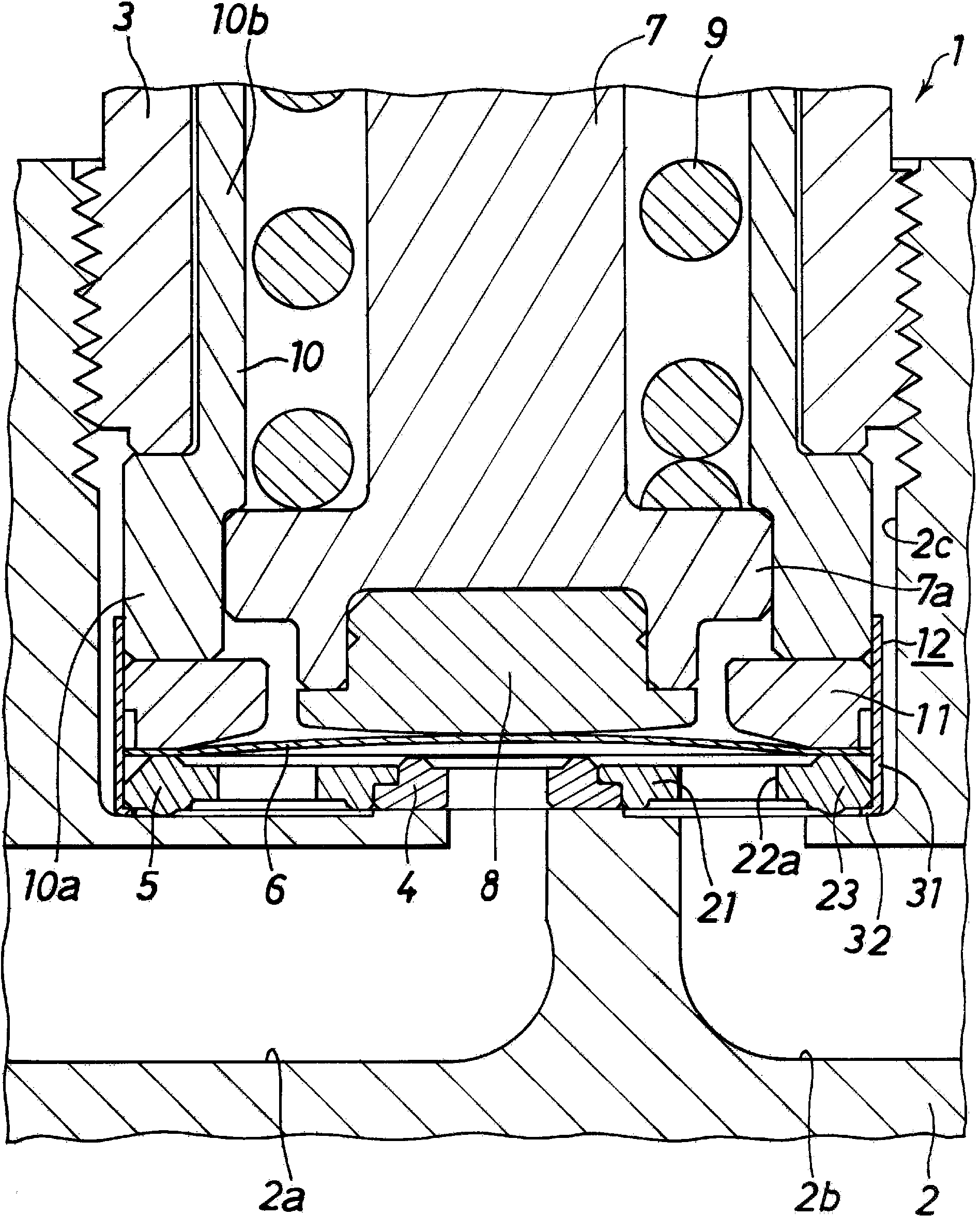
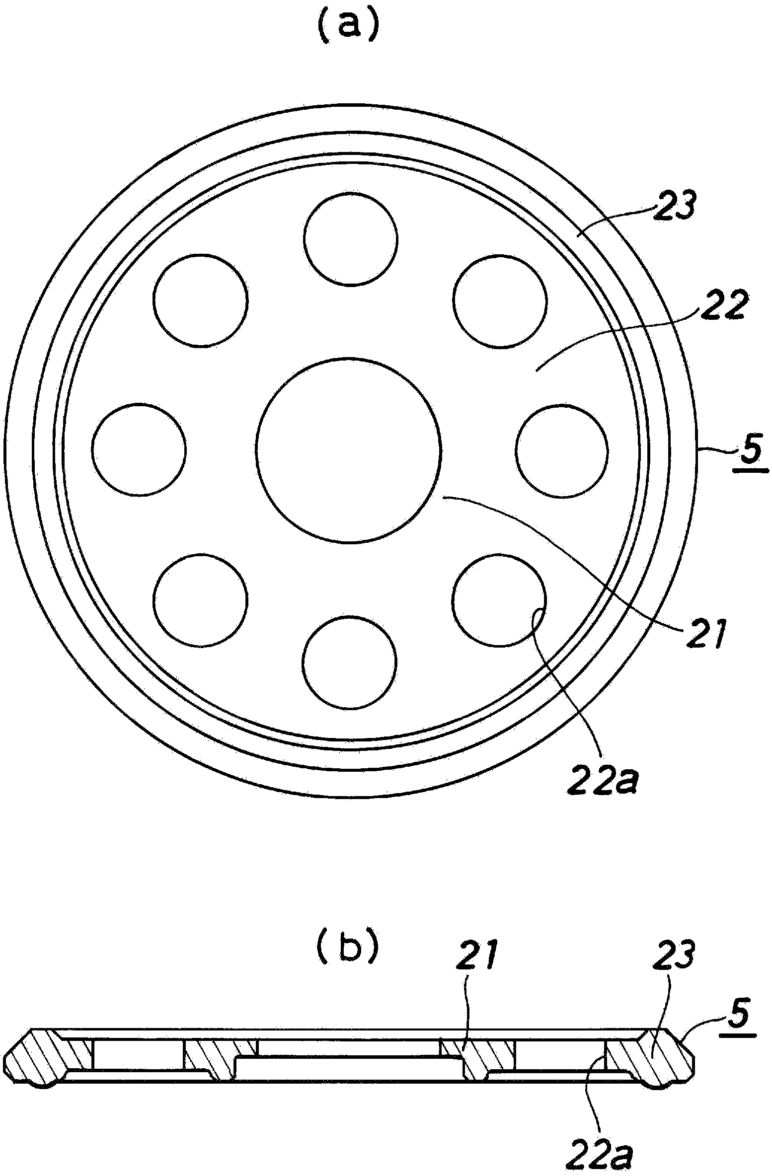
[0035] figure 1 Showing one embodiment of the diaphragm valve of the present invention, the diaphragm valve 1 includes: a block-shaped valve body 2 having a fluid inflow passage 2a, a fluid outflow passage 2b, and a recess 2c opening upward; A cylindrical valve cover 3 screwed and extended upward; an annular valve seat 4 provided on the periphery of the fluid inflow passage 2a; a valve seat provided on the outer periphery of the valve seat 4 in the valve body 2 and holds the valve seat 4 The retainer 5; the diaphragm 6 that is pressed or separated from the valve seat 4 to open and close the fluid passage 2a; the valve stem 7 has a diaphragm pressing member 8 that presses the central part of the diaphragm 6 at the lower end so as to be able to move freely up and down. Insert into the bonnet 3 in the same way, and press and separate the diaphragm 6 relative to the valve seat 4 ...
PUM
 Abstract
Description
Claims
Application Information
 - R&D
- Intellectual Property
- Life Sciences
- Materials
- Tech Scout
- Unparalleled Data Quality
- Higher Quality Content
- 60% Fewer Hallucinations
Browse by: Latest US Patents, China's latest patents, Technical Efficacy Thesaurus, Application Domain, Technology Topic, Popular Technical Reports.
© 2025 PatSnap. All rights reserved.Legal|Privacy policy|Modern Slavery Act Transparency Statement|Sitemap|About US| Contact US: help@patsnap.com