Apparatus and method for monitoring of welding joints with in-situ sensors

a technology of in-situ sensors and apparatus, applied in the field of welding technology, can solve the problems of large economic losses, catastrophic consequences, and failure of welded structures, and achieve the effect of preventing disaster accidents and optimizing maintenance efficiency

Active Publication Date: 2020-09-15
BROADSENS CORP JIAXING
View PDF12 Cites 0 Cited by
  • Summary
  • Abstract
  • Description
  • Claims
  • Application Information

AI Technical Summary

Benefits of technology

[0021]The invention has the following advantages: it enables monitoring of the status of the welding joint, tracking the occurrence and expansion of the welding defect, and determining the position and severity of the defect in real time while the equipment is in service. The invention can optimize the maintenance efficiency, change the periodical manual inspection to automatic scheduled and real-time and on-demand monitoring, and effectively prevent disaster accidents.

Problems solved by technology

When an equipment is in operation, the endurance of the welding joint is far lower than that of the base metal, and the welded structure may suffer from fatigue failure due to impacts such as dynamic loads.
The formation and expansion of fatigue failure can be difficult to detect, and fatigue fracture typically occurs in a short time, causing great economic losses and catastrophic consequences.

Method used


Image

  • Apparatus and method for monitoring of welding joints with in-situ sensors
  • Apparatus and method for monitoring of welding joints with in-situ sensors
  • Apparatus and method for monitoring of welding joints with in-situ sensors

Examples


embodiment 1

[0038]In embodiment 1, the apparatus for scheduled, real-time, or on-demand monitoring of welding joints includes an ultrasonic actuator T, an ultrasonic receiver R, a signal processing unit, and a control unit. The signal processing unit can be a single chip microcomputer, and the control unit can be an FPGA, a DSP chip or a single chip microcomputer. The signal processing unit can also be integrated with the control unit on a single chip microcomputer or FPGA. The control unit may generate a schedule or on-demand command for monitoring welding joints.

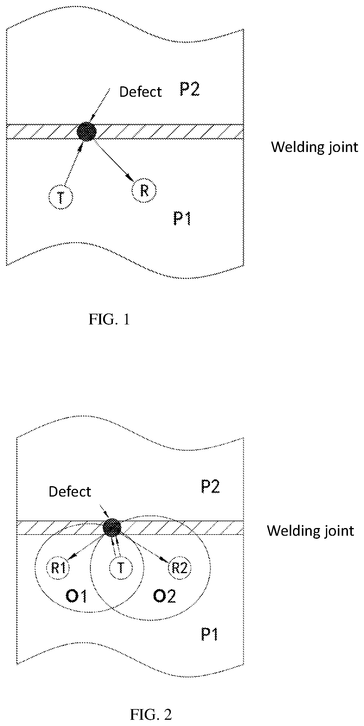
[0039]In FIG. 1, T is an ultrasonic actuator, R is an ultrasonic receiver, and P1 and P2 are two structures welded together through a butt joint. Actuator T and receiver R are mounted on structure P1.

[0040]The following is the working principle of the apparatus for scheduled, real-time, or on-demand monitoring of welding joints provided by the embodiment. The control unit controls the actuator T to emit ultrasonic signals. Some ultras...

embodiment 2

[0044]In embodiment 2, the apparatus for scheduled, real-time, or on-demand monitoring of welding joints includes an actuator T, a first receiver R1, a second receiver R2, a signal processing unit and a control unit. The signal processing unit can be a single chip microcomputer. The control unit can be an FPGA, a DSP chip or a single chip microcomputer. The signal processing unit can also be integrated with the control unit on a single chip microcomputer or FPGA.

[0045]In FIG. 2, T is an ultrasonic actuator, R1 is a first ultrasonic receiver, R2 is a second ultrasonic receiver, and P1 and P2 are two structures welded together through a butt joint. Actuator T, receiver R1, and receiver R2 are mounted on structure P1.

[0046]The following is the working principle of the apparatus for scheduled, real-time, or on-demand monitoring of welding joints provided by the embodiment. The control unit controls actuator T to emit ultrasonic signals. Some ultrasonic signals are reflected from the wel...

embodiment 3

[0052]In embodiment 3, the apparatus for scheduled, real-time, or on-demand monitoring of welding joints includes a first ultrasonic actuator T1, a second ultrasonic actuator T2, an ultrasonic receiver R, a signal processing unit and a control unit. The signal processing unit can be a single chip microcomputer. The control unit can be an FPGA, a DSP chip or a single chip microcomputer. The signal processing unit can also be integrated with the control unit on a single chip microcomputer or FPGA.

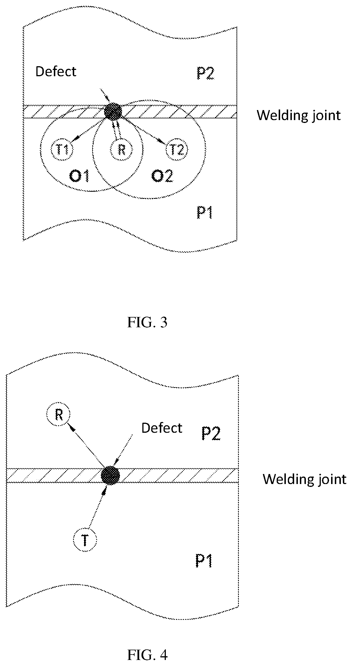
[0053]In FIG. 3, T1 is a first ultrasonic actuator, T2 is a second ultrasonic actuator, R is an ultrasonic receiver, and P1 and P2 are two structures welded together through a butt joint. Actuator T1, actuator T2, and receiver R are mounted on structure P1.

[0054]The following is the working principle of the apparatus for scheduled, real-time, or on-demand monitoring of welding joints provided by this embodiment. The control unit controls actuator T1 and actuator T2 to emit ultrasonic signals....


PUM

PropertyMeasurementUnit
distanceaaaaaaaaaa
temperatureaaaaaaaaaa
sizeaaaaaaaaaa

Abstract

The present invention discloses an apparatus and method for scheduled, real-time, or on-demand monitoring of welding joints with in-situ sensors. The apparatus includes at least one ultrasonic actuator, at least one ultrasonic receiver, a control unit, and a signal processing unit. The control unit controls the ultrasonic actuators and the ultrasonic receivers. The signal processing unit determines the status of the welding joint based on the ultrasonic signals reflected from or transmitted through the welding joint. The invention enables monitoring of the status of the welding joint, tracking of the occurrence and expansion of the welding defect, and determining the position and severity of the defect in real time while the equipment is in service. The invention can optimize the maintenance efficiency, change the periodical inspection to automatic and real-time monitoring, and effectively prevent disaster accidents.

Description

CROSS-REFERENCE TO RELATED APPLICATION[0001]This application claims priority to Chinese patent application Ser. No. 201811005844.X, filed on Aug. 30, 2018, the entire content of which is incorporated herein by reference.FIELD OF INVENTION[0002]The present invention generally relates to the field of welding technology and more particularly to an apparatus and method for online monitoring of welding joints.BACKGROUND OF THE INVENTION[0003]Welding is one of the most fundamental processes in the manufacturing industry and is widely used in many applications, such as trains, aircrafts, ships, power plants, chemical processing plants and many others. The quality control of welding joints has direct impacts on the safety of the structure and is an important part of structural quality management. When an equipment is in operation, the endurance of the welding joint is far lower than that of the base metal, and the welded structure may suffer from fatigue failure due to impacts such as dynam...

Claims


Application Information

Patent Timeline
Patent Type & Authority Patents(United States)
IPC IPC(8): G01N29/32G01N29/07
CPCG01N29/326G01N29/07G01N2291/267G01N2291/0289G01N2291/103G01N29/04G01N29/048G01N2291/011G01N2291/0231G01N29/069G01N29/2412G01N2291/044G01N2291/048G01N2291/105
Inventor ZHANG, CHANGLIU, LEI
Owner BROADSENS CORP JIAXING
Why Eureka
Try Eureka